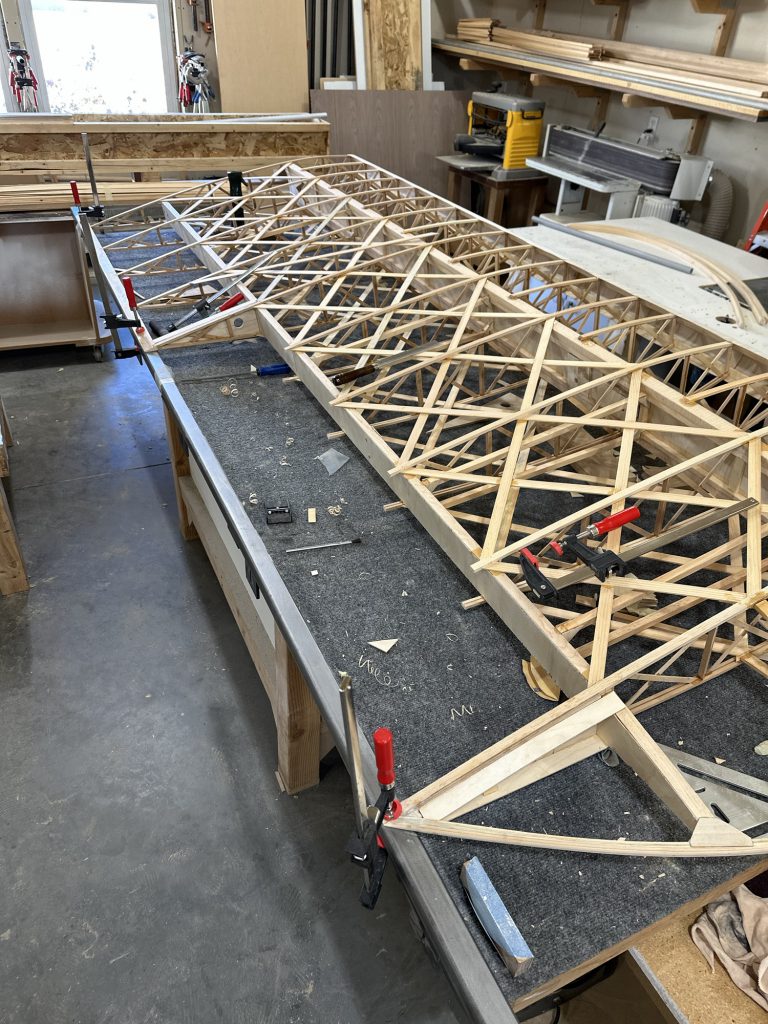
I’ve spent a couple hours this week getting bolt length sorted out and getting some of the wing fittings attached.
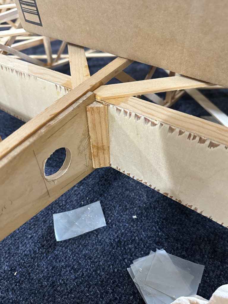
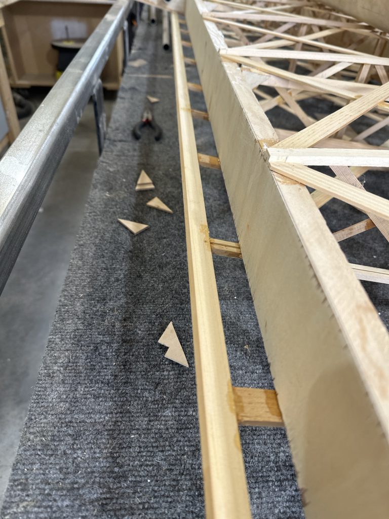
My strategy for the wing attach fittings was to make one of each type of fitting, pilot drill the holes with a 1/8″ bit, and use those to mark the location of the holes in the wing spars. Those holes got drilled on a drill press using Forstner bits. Then I cut the rest of the fittings, used the first ones as templates for drilling them, and figured all of the holes should line up.
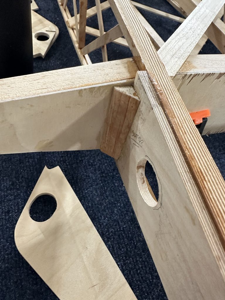
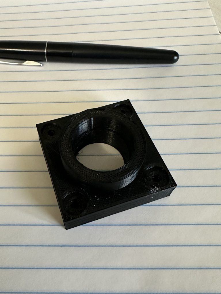
Well – they’re close. I’m not a machinist, nor am I using tools techniques of suitable precision to produce perfect parts. For example, when looking at the CAW2A wing root mounting brackets, the holes are not perfectly aligned – so there’s a top and bottom to those, meaning until I figured that out it took a few tries to get everything lined up right. No big deal.
Then I discovered that one of the holes isn’t drilled perfectly square. It’s only off by maybe .010 total, but just enough that you can’t run a bolt through the forward bracket, the bushing, and the aft bracket without interference. If the bolts were just going through holes drilled in the wood of the spar, it would be fine – but the bushings are a snug fit, I had to do a little adjusting of that hole to get everything to fit properly.
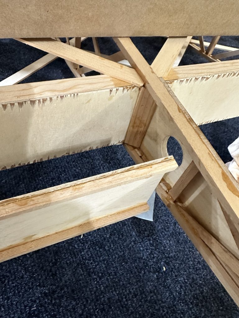
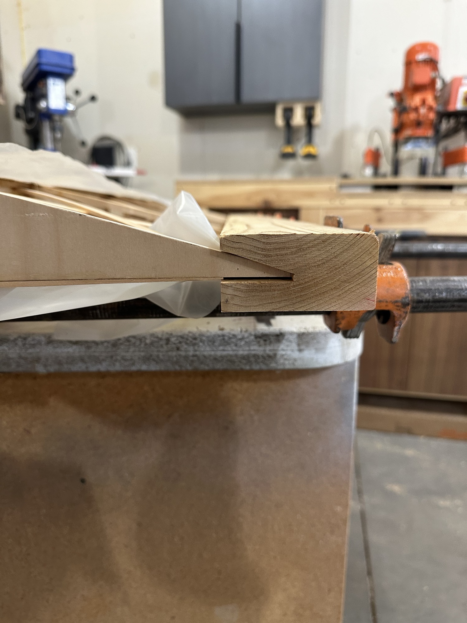
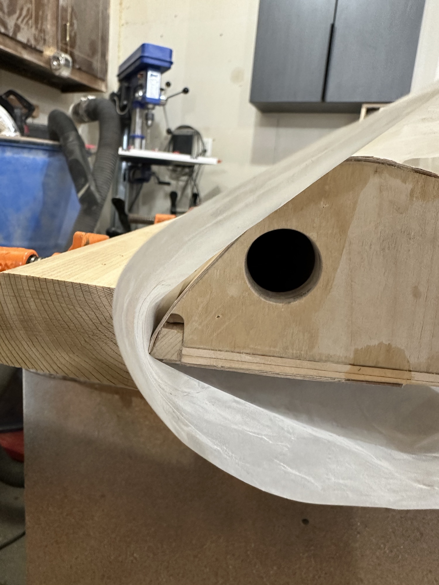
We finally got the bottom of the aileron leading edge routed so that it’s now in its final state. When fitting the aileron and checking travel, I discovered that I’d messed up just a little when up finishing out the aileron bay. On the first wing, I’d positioned the top beveled strip with the aileron in place, and checking clearance per the plans. On this one, I just measured the first wing and matched it. I don’t have enough up travel on this aileron. After a little more investigation, it’s just the ends that interfere, so easily cleaned up with a couple minutes of work with the razor plane. I’ll need to pay closer attention on the next two wings. I’m thinking just use a length of 1/4″ shim stock to set the spacing with the aileron solidly fixed in its final location.