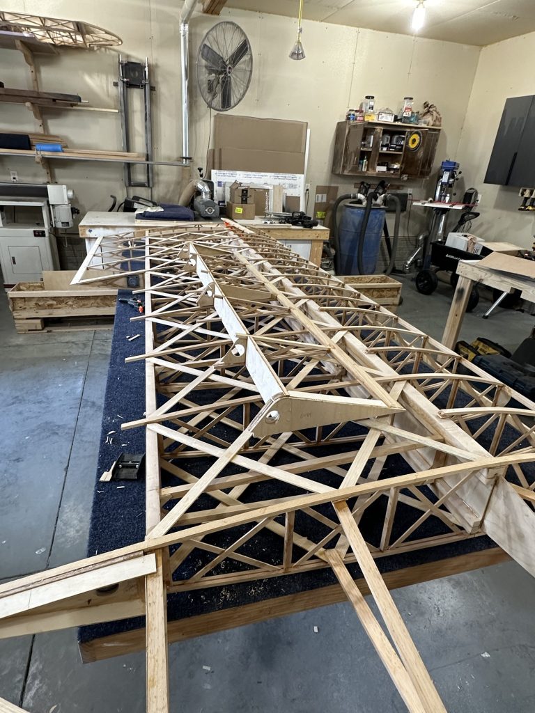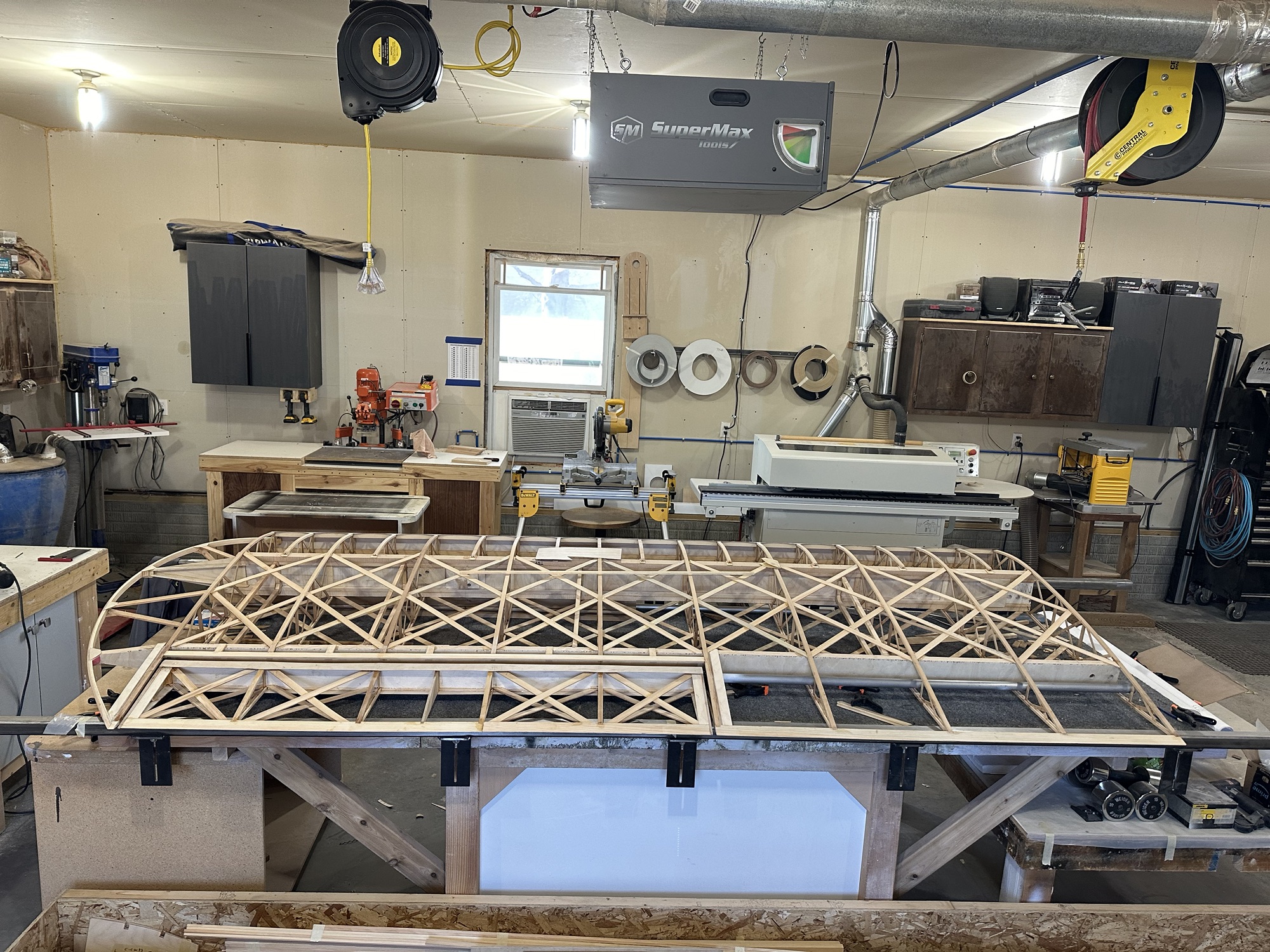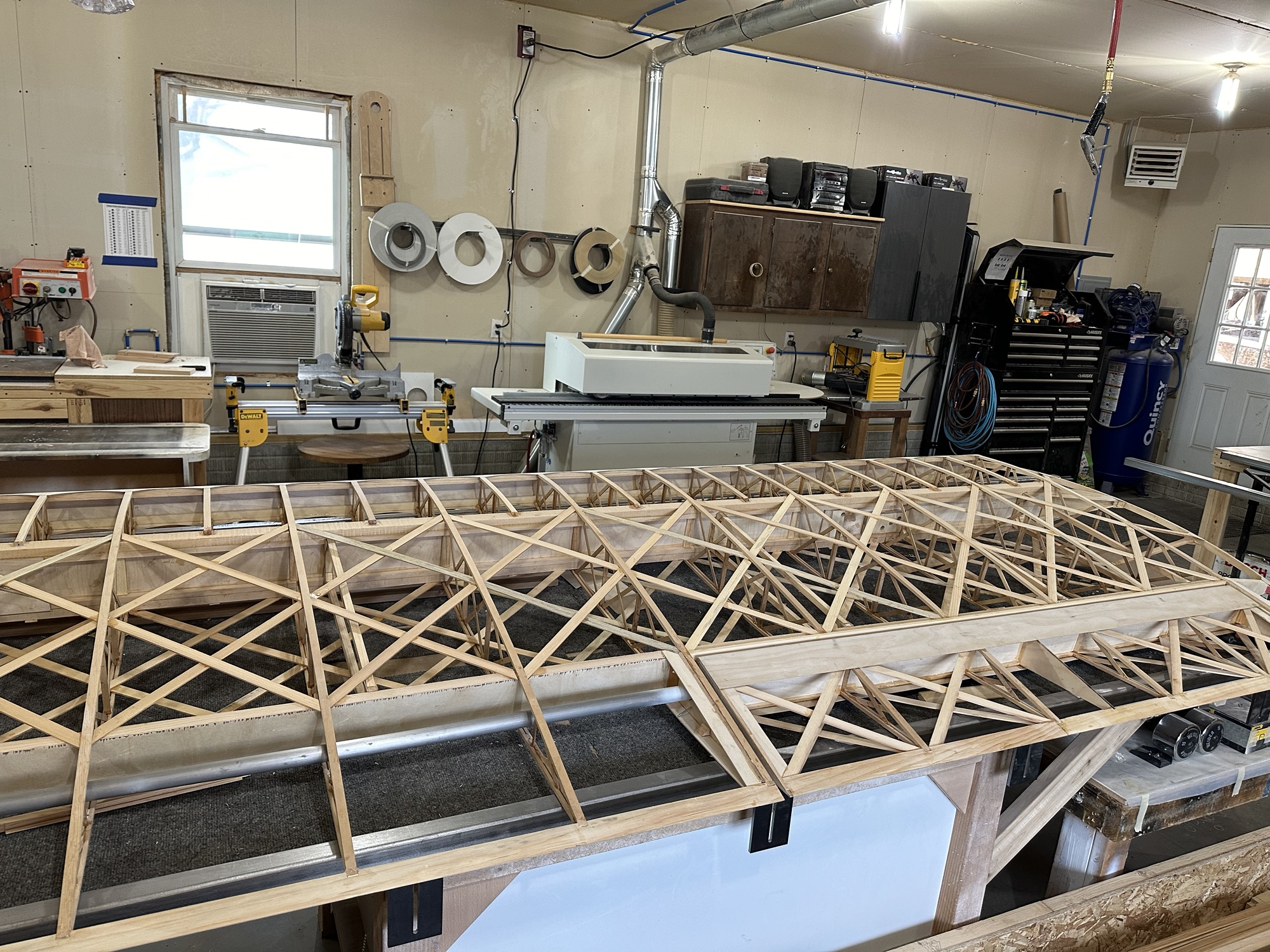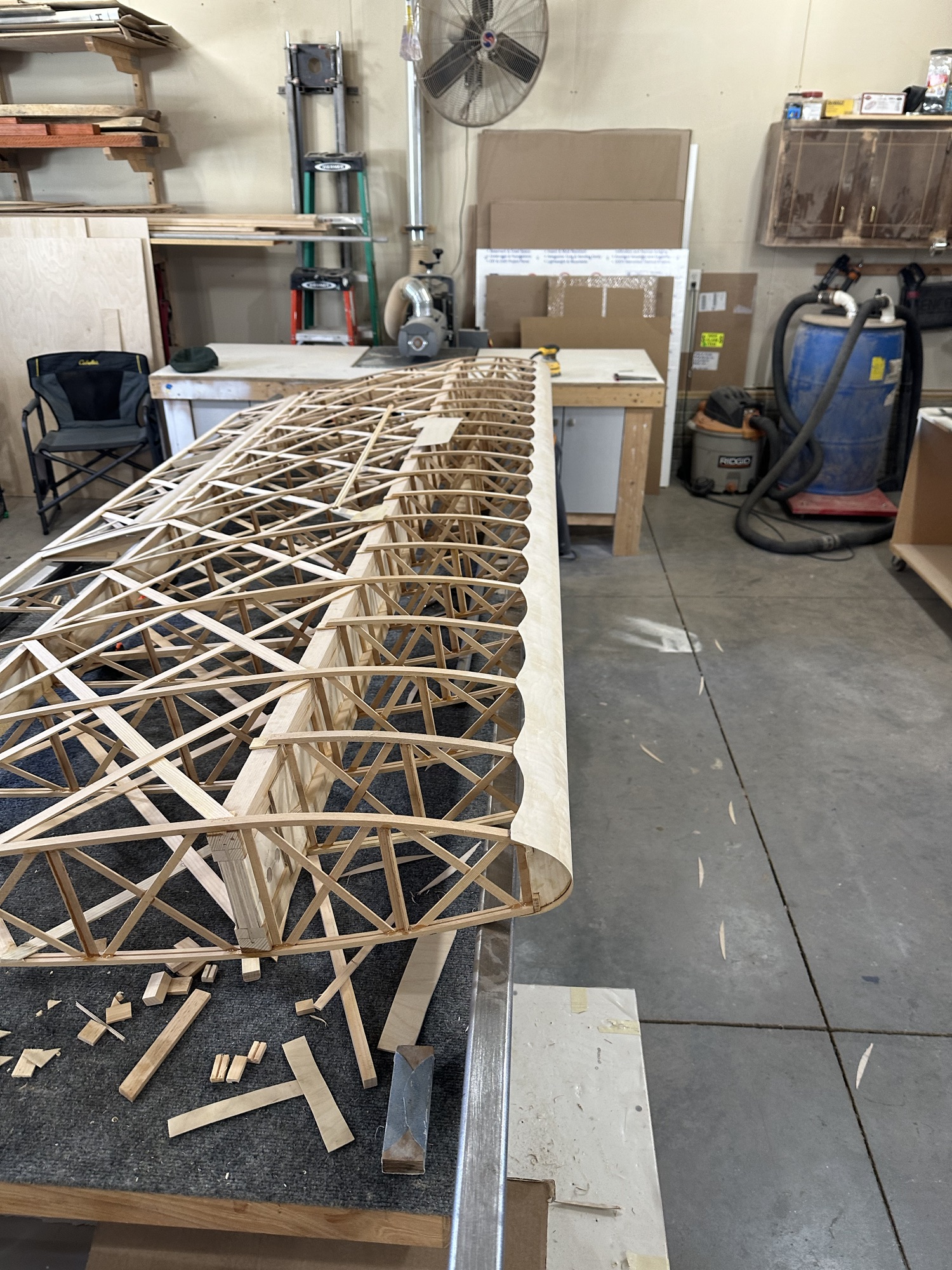
I keep finding little things that still need to be done on this wing. At least it won’t take as long to do the next one. I’ve been getting over there nearly every day, but the little bits of work here and there didn’t seem worthy of a complete build log post. But since the last update:
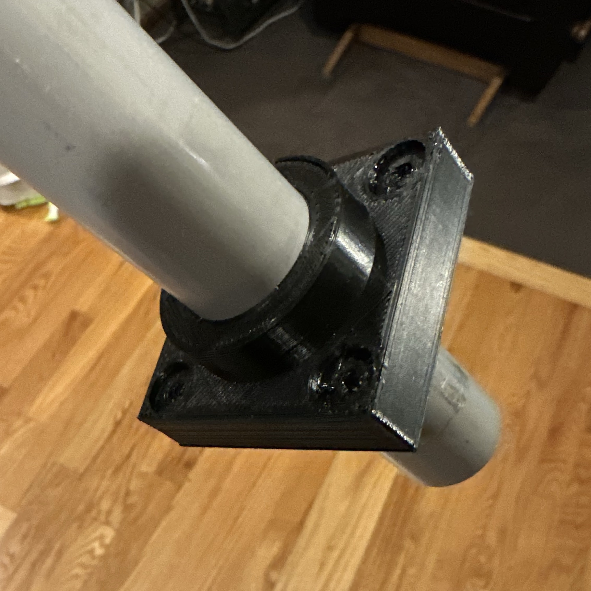
- Cleaned, primed, and drilled the fittings for the upper/lower aileron pushrods
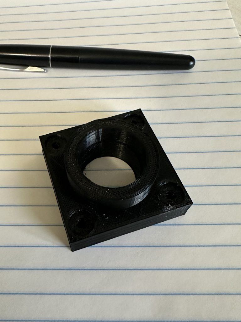
- Located and drilled holes for the aileron bearing block screws
- Managed to punch a hole in the aileron LE skin, and glued a patch over that (will need to smooth it out with some micro)
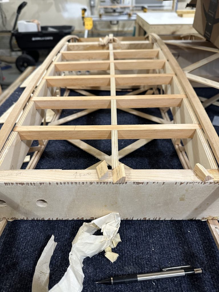
- Worked to trim the upper aileron bay piece to get full UP travel on the aileron
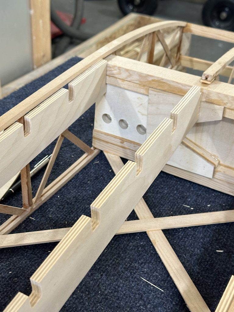
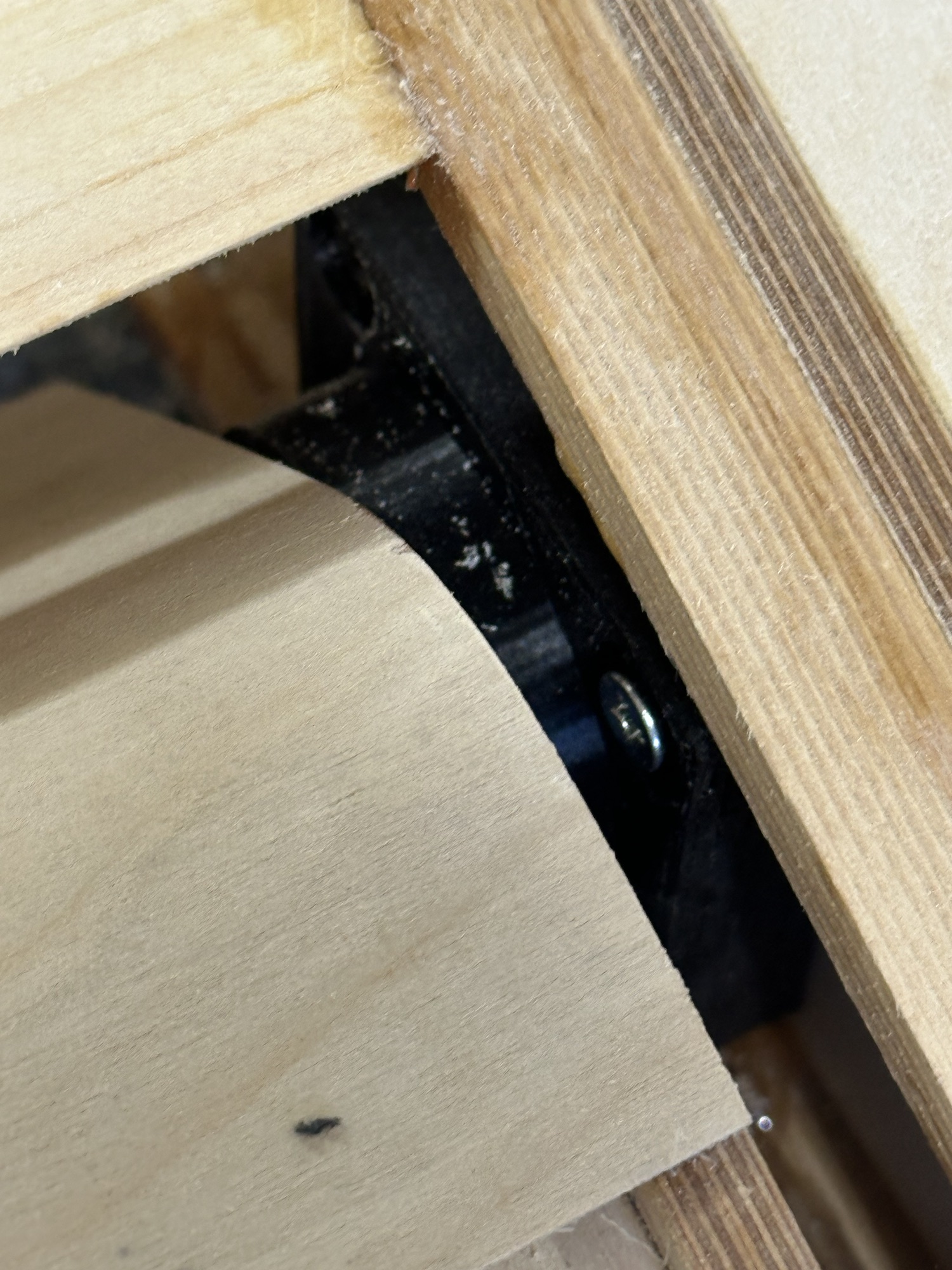
I also found that the aileron DOWN travel is restricted by one of the bolts for a fitting on the rear spar. I recall reading that the rear spar thickness was changed from 1/2″ to 3/4″ at some point, and that causes interference. The aileron should have 22 degrees travel in both directions; I get about 15 – 17 degrees down right now. It would be less if the aileron and wing were covered. I need to dig though the plan supplements and find the section that talks about that and see how to fix it. The obvious choice would be to notch the lower front corner of the aileron leading edge to clear the bolt head, but I’d really prefer some other solution… it sure would have been nice for whoever did the plan changes along the way to have properly documented this stuff on the drawings themselves, rather than just tacking on random pages with these “Oh, by the way…” notes (which are themselves occasionally wrong).