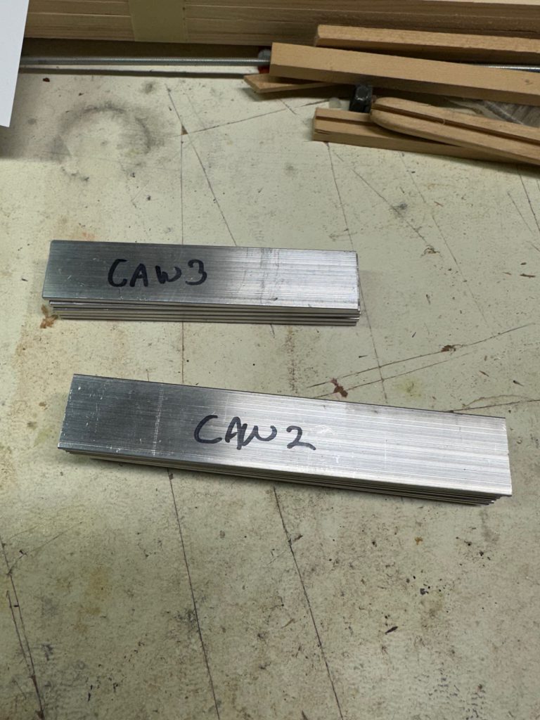
So, I found the plan supplement that talks about the aileron interference. Written in 2010 — seven years before I bought my plans — it notes that the rear spar was changed at some unknown point in the past, by someone, but never really documented, and the “updated plans will be sent out as they are available”. Which, apparently, they never were and probably still aren’t. Then it talks about plans delivered electronically (which they weren’t, and to my knowledge weren’t offered) having an updated sheet with new dimensions for the ailerons. It also says that this is only an issue with the upper ailerons hitting the CAW9 bracket. Uh, no. The lower aileron hits the head of the bolt holding the CAW3 bracket. There is one sheet that seems to show an upper aileron, with no dimensions to be seen anywhere. Wonderful.
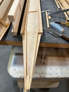
So what’s their brilliant solution for fixing an already built aileron? Simply move it rearward to clear the bracket – this means take a hole saw to the wing to move the torque tube back in order to move the aileron. Then just cut off the trailing edge to match the rest of the wing, and sand all of the aileron ribs to match the contour of wing at the new location. Oh, and that’s probably going to remove enough rib cap material that extra bracing will be required… How many ways can this be wrong?
I get the impression that whoever wrote all of that has never actually built a Celebrity wing with 3/4″ rear spar caps. Meaning, whoever it was hadn’t built a Celebrity wing to check this stuff out since 2010. Come on.
I’m currently evaluating whether notching the lower leading edge of the aileron is an option. The actual aileron spar wouldn’t be affected, and the torque tube runs the entire length of the aileron, so it’s not like it could fold up and depart the aircraft. Still, I don’t want to weaken the thing and take the risk of cracking or anything, especially since this structure will all be under fabric and not easily inspected. Stu seems to think it wouldn’t weaken the structure, but he’s a carpenter and cabinet guy, not an engineer (and neither am I).
I’m going to have an actual engineer look at this and give me his opinion. I could always add a layer of 1/32 or even thicker ply if needed, but my gut feeling is that it’s not going to weaken anything enough to matter. In the mean time, I’ll keep pushing on, but this is kind of a kick in the nuts, to be honest. I’m sure a year from now I’ll look back and marvel at how little it actually mattered. I would feel sorry for anyone buying a set of plans now at over $3K and probably still not updated… I hope the new owners of the Fisher IP take the time to fix this kind of stuff.