Boy, I’m bushed!

Today I took the wing brackets over to the shop, sorted them all out, and re-marked them so I could tell one part from the other. There are seven (I think) different bracket types. The acid etch solution had removed all of the markings, along with other stuff.

I sorted out which brackets are needed for the right lower wing that’s on the bench, and checked all of the bolt sizes for proper fit. All are acceptable, if not perfect. I have AN4-24A bolts (1-15/16″ grip length) for the main spar root attachment brackets; I could have used AN4-23A (1-13/16″ grip length). It’s not a problem; a couple of AN960 washers do the trick and are a perfectly acceptable solution. On the rear spar N-strut (outer end) brackets, the AN4-16A bolts are a tad long; I could have used -15A. Two AN960 and one AN960L are fine. As a mental exercise I calculated the weight savings if I ordered the shorter bolts. The shorter bolts would weigh about half an ounce less (total per wing); the washers would bring that up to just a smidge over half an ounce — .53 ounce, or about 15 grams per wing. I can live with that.

But I digress. I got all the remaining bushings cut. Once I wrapped my head around that fact that the bushings do not need to be cosmetically and dimensionally perfect, but just need to be “flush or slightly below” the face of the wood per the plans, things went a little quicker. I pulled the 24 tooth per inch metal blade from my bandsaw and replaced it with a 10 TPI wood blade, which is fine for thin wall AL tubing like this. I set up the miter gauge and fence for the length I wanted. The tubing cut-off end was snagging the blade teeth; Stew suggested a spacer on the rip fence that extends just shy of the blade. That did the trick! Now the cut-offs roll out of the way. I cut one piece and tested for fit in the hole; once that was verified I was able to set the fence once and cut as many pieces of each diameter tube as I needed. Easy peasy. That will save hours of build time.

Now I need some etching primer for the brackets, and spar urethane for the wood, and I can get everything installed and call this wing done.

Oh, after I cut the bracket for the aileron connecting rod.

And get the bearing block holes drilled.

And… whatever else I’ve forgotten.

Wing metal parts

Over the past couple of days I’ve been collecting, drilling, and prepping the aluminum wing attachment parts. These are a collection of pieces cut from 6061 and 2024 AL bar stock. They will be used to attach the wing spars to the fuselage, attach flying and landing wires, and attach the N struts, and connect the upper and lower ailerons. Each one must be cut from the raw bar stock, drilled for bolts, and some of the ends rounded. I’ll do some sort of finish to prevent corrosion. I have some Alodine left over from when I was building the RV-12; if it’s still usable I’ll use it. If not, I’ll most likely buy some.

More than once the instructions have caused a little bit of panic. For example: Yesterday I drilled all of the holes in the attachment brackets to their final quarter inch (0.250) size. I remember that I’m short some pieces, but didn’t remember which ones or how many. I’m also unsure of which ends of which brackets need to be cut and sanded round. This morning I looked at the plan revision sheets that show the drawings for the parts… and saw that the drawings call out all of the holes to be 0.1875″. Panic!! Holy moly, did I just ruin all of those parts and waste all of that work? Oh, wait. I’d made little 3D printed pieces to help mark the ends for cutting… and those have 1/4″ bosses to fit the holes, so I planned 1/4″ holes before. And a 3/16 hole would fit an AN3 bolt. I’m pretty sure the plans call for AN4 bolts everywhere, and there’s no way in hell I’d be comfortable with wings held on with AN3 bolts…

Back to the wing spar plans… Yep. AN4 bolts and 1/4″ ID bushings everywhere. The supplemental drawings are incorrect or out of date, no big surprise. Back to work.

I did manage to badly mis-drill one of the CAW9 brackets, so that’s scrap — but it really doesn’t matter in the long run. I came up a little short on the 3/16″ 2024 stock needed for some of the parts, so I’ll need to buy another 12′ length anyway. It’s an odd size that is difficult to find on line, but fortunately my local supplier can get it for me even in single piece quantity. Even they don’t list it in their catalog. Most places only carry 2024 in 1/4″ thickness or more.

After inventorying my parts I need another 60″ or so of 2024 stock, and I only have about 3′ if that. Fortunately the parts I have on hand are enough for the two lower wings, so I can cut the bushings, buy hardware, and attach all the pieces on the two wings I have built and get them finished before moving on to the upper wings.

I got over to the shop to make sure the bolt lengths called out in the plans were OK. I’m glad I did. IN each case I decided to bump the bolt up one number to get the next longer grip length; the exception was the three bolts on each wing that attach the CAW-4 landing wire brackets. Those were specified nearly half an inch short; I had to go from AN4-20A to AN4-24A to get the right grip length. I’m glad I checked. I also ordered a couple dozen standard and half-thickness AN960 washers to get everything done up right. The hardware is ordered, now I just need to get the bracket ends done and get them prepped for installation.

A couple days’ work

Saturday: Ripped the CW37 parts down to the proper 1/4″ thickness. These are the strips with one beveled edge that go in the top and bottom of the aileron bay. The parts I got are 1/2″ thick, which won’t work anywhere. Ripped them all down to 1/4″ so I don’t have to do that again for the other two wings. With them cut to the right thickness, I cut one to length and glued it into the bottom of the aileron bay.

Then I discovered (or confirmed) that I’m an idiot… there were a couple of missing aileron pieces that I found in the bottom of the parts crate. Had I installed them in the first place, the little triangular braces would not have been needed. It’s no big deal; I was able to slot the nose skin support spar and get them glued in.

Today: Got the nose skin plywood glued onto the front of the wing. I think there are now about 70 or more clamps on the wing. I had planned to glue the top aileron nose skin in place, but that’s going to take some more work. I see no way to get that ply to stay attached all the way around without some sort of clamping jig. Stu and I figured out a good arrangement, but I’ll need to get some MDF, ply, or pine scrap to cut them out of. I need seven sets of clamping blocks for the nose and trailing edge, then I can use bar clamps to hold everything in place.

I also found that a few batches of glue I mixed up over the past week or two were probably not the greatest. My T88 had started getting cloudy — a sign that the resin is starting to crystallize. Some of my test pieces failed at the glue joint, albeit with a lot of force required, instead of the wood failing before the joint. I’m not really concerned about this. All of the affected glue was used for either the wing walk or adding corner blocking and gussets to the wingtip bow. The wing walk pieces are fully supported and there will be no bending, twisting, or pulling loads applied. The glue is strong, just not AS strong as what I’ve used everywhere else.

I have since tossed the syringe of clouded resin, warmed the rest of my resin supply until it’s crystal clear, and verified that test pieces now all break well into the wood rather than at the glue line. I’ve tried spruce to spruce, which tore apart well into the wood, and spruce to plywood which ripped the plywood apart.

CAW2 brackets

Over the past couple of days I’ve gotten all 14 of the CAW2 brackets shaped. I had drilled all of them already, but the ends needed to be rounded off. One end of each will be hidden inside the wing, but some will have one end exposed so I wanted them looking decent.

I designed a radius guide to help with the bandsaw and sander. It’s just a 1″ diameter disk, with a short 1/4″ button on the center of one face. Stick the button into the hole on one end of the bracket, and the guide is there to show a 1/2″ radius all the way around. My original idea was to use them to scribe a line to follow when finishing the ends. I had 3D printed a couple of them, and found it was just as easy to just leave it in place and work around the edge. Inevitably, of course, you end up nicking one so I printed up a batch of 9 more. I used 3 of them to finish off the CAW2 brackets.

Given that there are a bunch of other brackets to finish, I’ll definitely try the scribed line approach as well. Overall, though, I’m pleased with the results. I used the bandsaw to lop off the corners, then shaped the ends with a disc sander and finished them on a Scotch-Brite wheel. I had planned to paint them, but I may not. I’ve still got a batch of metal etch and Alodine (Bonderite 1201, to be precise), so if it still works I’d like to just give them a conversion coating that weighs nothing; that way they are protected from corrosion but only the exposed parts get paint. I’ll probably try a test piece to see if the Alodine still works; if not, I’ll get some self-etching primer and use that instead.

Miscellaneous work

Today came and went without mixing up any glue. I sorted out the nose plywood, then went through all of the aileron pieces and got them cleaned up, marked, and re-taped for the three remaining ailerons. I got the aileron spar web and marked it for the notches to clear the ribs, then brought it home and started cutting those notches on the bandsaw. I pulled a wingtip bow down and checked its fit; it looks like minimal trimming will be needed.

I also collected all of the aluminum pieces I had at Stu’s shop and brought them home, and cut the ends on the bandsaw. They’re all CAW2 pieces, I think — I need to dig out the rest of the pieces and get them all drilled and finished off. I’ll finish them on the belt sander and Scotchbrite wheel before priming them. My little 3D printed guide button worked great for this. I don’t recall if I described it or not, but it’s just a 1″ diameter by 1/8 thick disk, with a 1/4″ diameter by 1/8 thick nub in the center. Put the little piece in a 1/4 bolt hole, and the larger piece gives you a perfect guide for shaping the end of the bracket with a 1/2″ radius. They’re disposable if you nick or break one, and only take a little while to print up. I’ll probably print a few more in case I destroy any while using the belt sander.

I spent some time trying to determine whether the wing walk pieces will be of any use to me or not. The plan sheet and plywood supports all seem to be made for some earlier version of the wing. The notches on the supports don’t work (or even come close to working) with the root blocks on the main spar or rear spar. The forward plywood bits are too long, and even if cut off don’t match the curve of the wing ribs. There are supposed to be three installed forward of the spar — but that would only work if I removed one of the false ribs. I still don’t know what I’ll do for the wing walk. I do know that 1/4 plywood for the rear portion would need some curve in it, and I’m not sure about that. The plan notes say to nail it in place until the glue dries… ::shrug:: This is why I’m considering a laminated layup with some wood and maybe a layer or two of carbon fiber.

Lower left wing, Day 2

I feel like we accomplished a lot today. This morning Stu and I unclamped the partially assembled wing and found that it was already quite stiff and of course perfectly square. The epoxy where the ribs were glued to the trailing edge material was pretty well stuck to the steel rail, but the careful use of a utility knife blade between wood and steel popped those spots loose. Next time we’ll use poly or waxed paper. Stu sanded the rail to remove the epoxy and applied a couple coats of paste wax.

We stood the wing panel on its nose and slid the main spar into place, then glued and pinned the ribs to the bottom of the spar. The first rib was placed flush with the end of the spar, and the rese were once again set in place using the 11.5″ gauge block that we’d used for the rear spar rib spacing. It perfectly matches the notch spacing on the trailing edge, so everything remains perfectly spaced and square. Once that was done, we rotated it back horizontal and re-clamped the trailing edge to the rail. Now I cut some short lengths of laminating strip material to act as shims between the spar cap and rib caps, so we glued and pinned the ribs to the top rib cap.

With that done, we glued the false ribs in place using a 5.5″ gauge block. Lile the main ribs, these were glued and pinned to the bottom of the spar, then shimmed, glued, and pinned to the top.

As I had some glue left over, I decided to attack the geodetic bracing. I hadn’t really intended to do it all, but in the end all of the top surface geodetic braces are glued and clamped in place. We’ll do the bottom surface after the compression struts are done. What remains is the compression struts, bottom geodetics, nose ribs and plywood, and ailerons. And that’s where it’s all going to get messy. When I modified the ribs to clear the rear spars in the upper wings, I inadvertently put the cross braces right where the aileron torque tubes need to go. Oops. Not a problem on the upper wing, but it is on the lower wing. I think my fix for this will be to simply remove the pair if X braces (that I just installed) on the non-aileron ribs, and glue on a side plate cut from 1/16 plywood to stiffen that part of the rib. Then I can just have a hole for the torque tube. This should make the rear portion of those ribs substantially stronger than using the geodetic bracing, and will be only very slightly heavier. The upper wings should not need this modification, only the lower wings.

The last two wingtip bows came off the forms and are ready to install, so we removed all the screws from the table and stacked them until it’s time to finish them off. We’ll likely sand the top and bottom surfaces to remove the excess epoxy, then run the outer edges through the router table for a 3/8 radius top and bottom.

Lower left wing assembly

I chose the lower left wing to start with since it is the simplest of the four. The lower right will get the wing walk, and the upper wings get a diagonal cut on the inboard bay.

This morning I pulled the first two wingtip bows from the forms; they look pretty good. I mixed up about 40cc of glue and started gluing up all of the strips for the second pair of bows. Had to mix another 10cc, so if I ever do this again I know it takes 50cc per pair of layups. I got them clamped into the forms and slid the table as far out of the way as possible.

The plans say to nail or screw a block of wood to the top of the bench, square with the trailing edge to set up the wing. Since we’re not building it resting on the bench, Stu and I squared up the first rib with the TE (which is clamped to a steel rail) and marked & clamped it to the other rail. After some debate, we decided to pull the main spar out temporarily. I needed to pull the TE of the rib from the notched TE stock to glue it, and with both spars in place it was nearly impossible to do so. The rear spar is a pretty snug fit in the ribs, btu the main has about 1/8″ of clearance so it’s relatively easy to slide out and back in.

Rather than a continuous piece of trailing edge material long enough to do a complete wing, this kit had four 8′ long pieces and four pieces roughly 4-1/2′ long, I cut the longer piece just inboard of the first aileron rib, and started one of the shorter pieces at that point. We got them aligned and clamped well enough that you can’t tell where the joint is if you sight down the trailing edge.

Stu cut a rectangular block about 6″ tall by 11-1/2″ wide, since that’s the distance in between each pair of ribs. With the first rib glued in and squared to the TE, it was then just a matter of using that gauge block to seat each rib exactly where it needed to be on the rear spar. Each rib was glued to the TE and rear spar, and a couple of 1″ micro pins shot through the rib cap to hold it in place while the glue cures. Working that way we got the entire set of ribs in place. We’ll let the glue cure and slide the main spar back in place tomorrow, glue the ribs to it, and attach the false ribs

I did some other work today, including trimming the false ribs so they’re ready to install.

Building the Wingtip Bows – and more

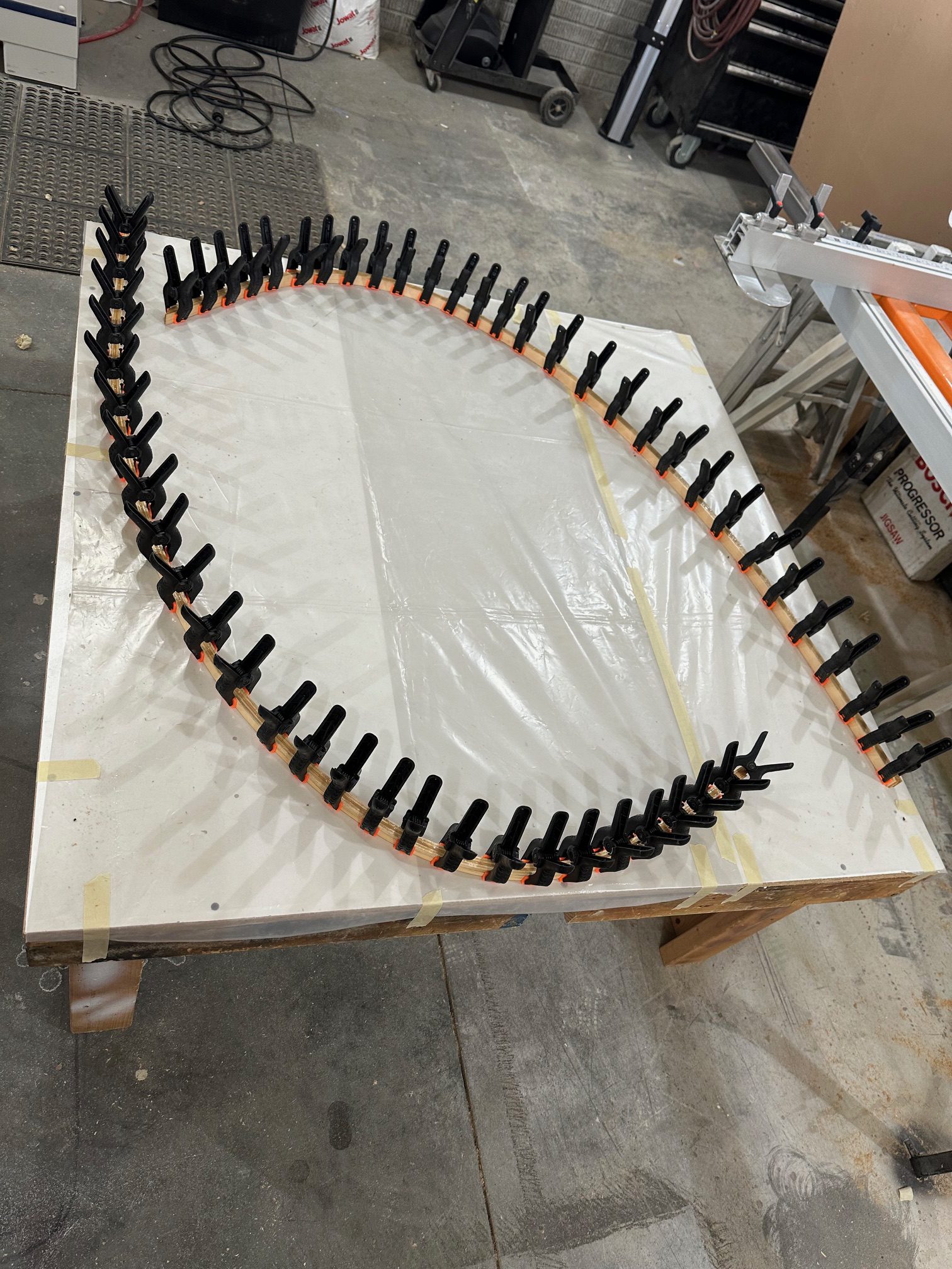
It’s really nice working in Stu’s shop with lots of room and plenty of work surfaces. One of those work surfaces is a 48″ square low table, with a 3/4″ melamine laminate top. It’s just the size needed for laying out thew wingtip bows. I started out by laying a large piece of cardboard out and taping the plans page over it. Then I used a sharp punch to poke through each of the nail locations on the plans to mark on the cardboard where they should be. Since I wanted to get two bows done at a time, I then rotated the plans page and marked a second set of nail locations.

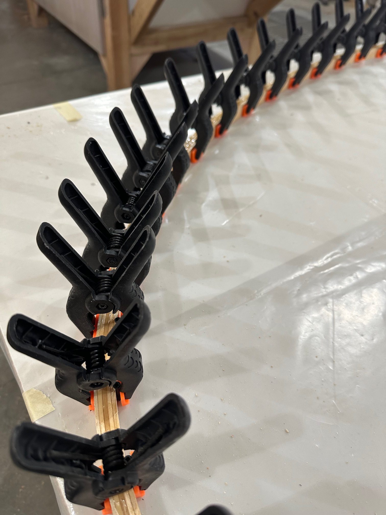
Rather than hammer nails into the tabletop, we taped some poly sheet and then the cardboard down onto the surface and drilled 1/16 pilot holes. Stu has a bunch of trim head screws, so we sunk those using a block of wood as a depth gauge so that the heads are just above the 3/4″ mark – since we’re laying down 3/4″ lamination strips. With all the screws in place we pulled off the cardboard, leaving the poly sheet and screws.

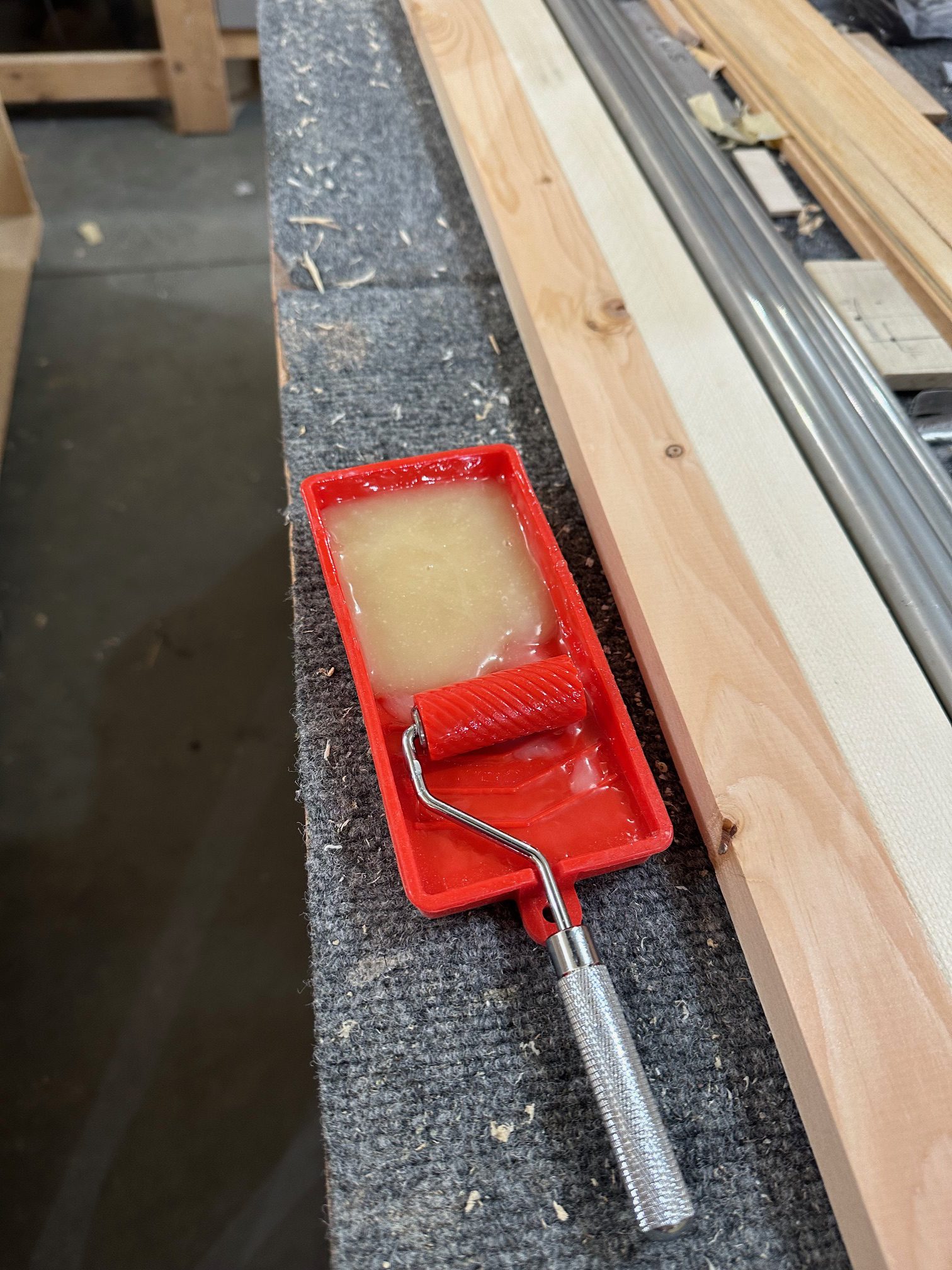
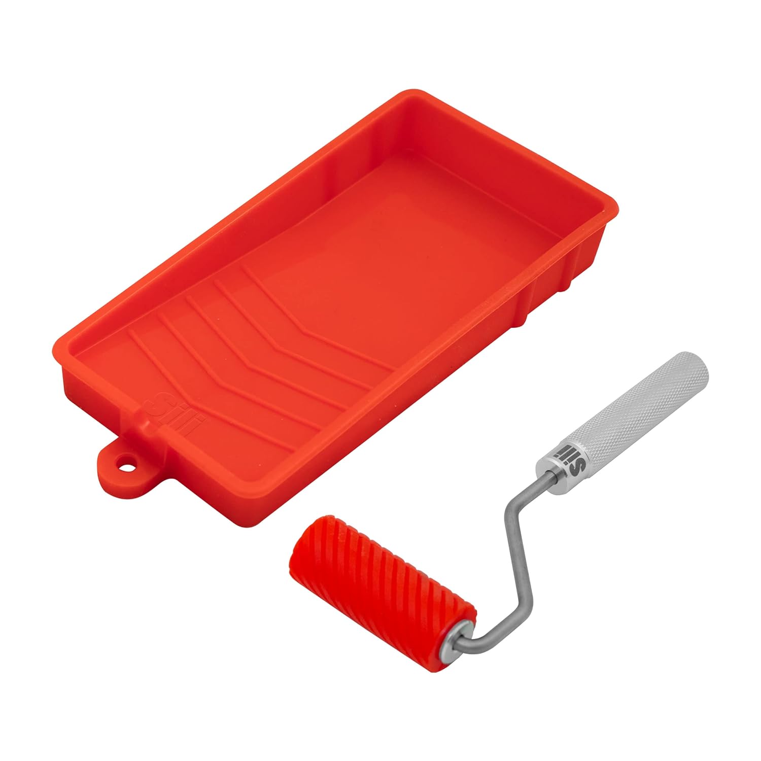
Knowing that I’d need to spread a lot of epoxy in a short amount of time, I bought a small silicone glue roller and tray. The tray is about 6″ long by 3″ wide, and the roller is a bit under 2″ wide and is grooved to hold more glue. Since it’s all silicone rubber, the cured epoxy just pops right off after use.

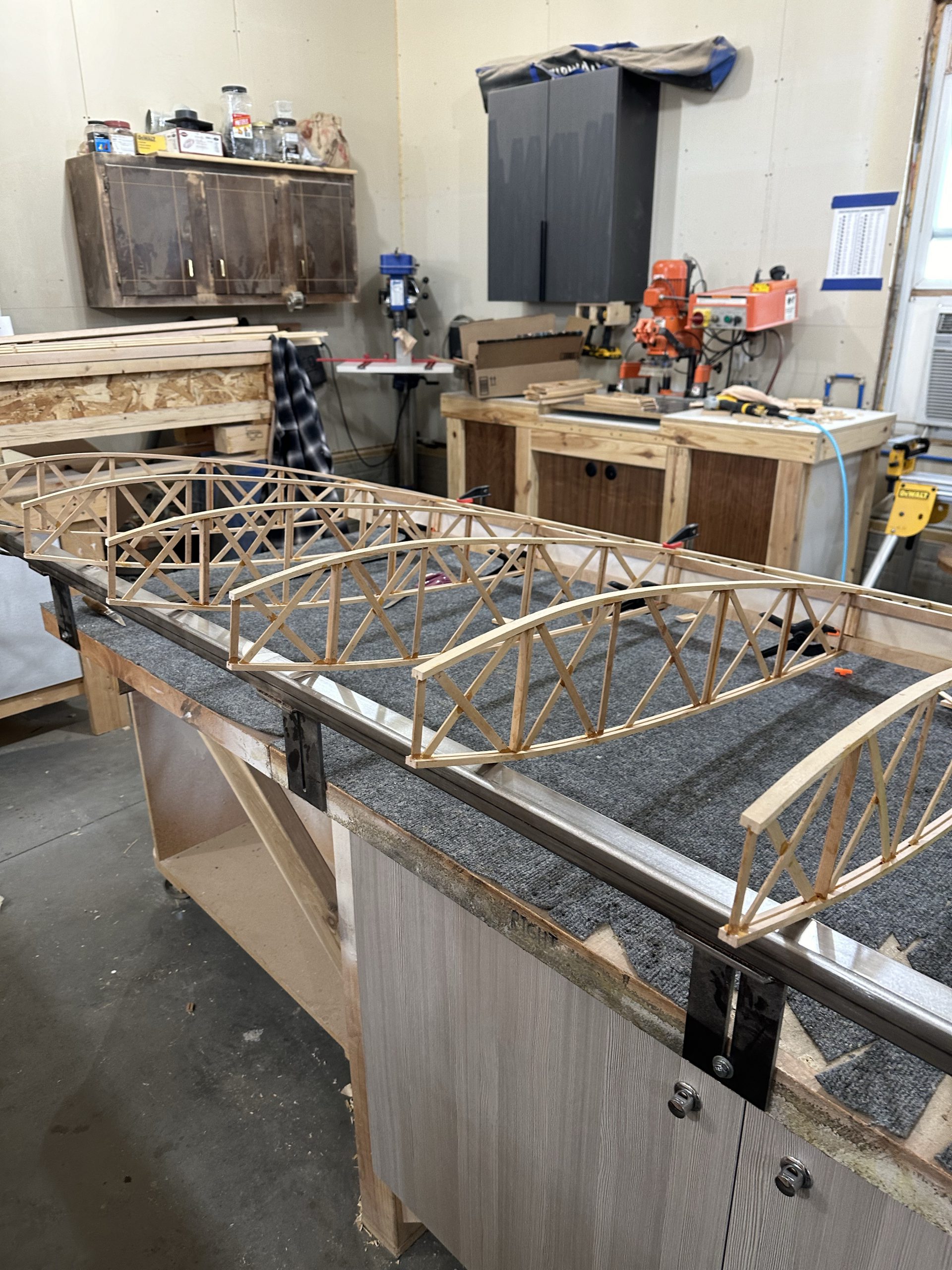
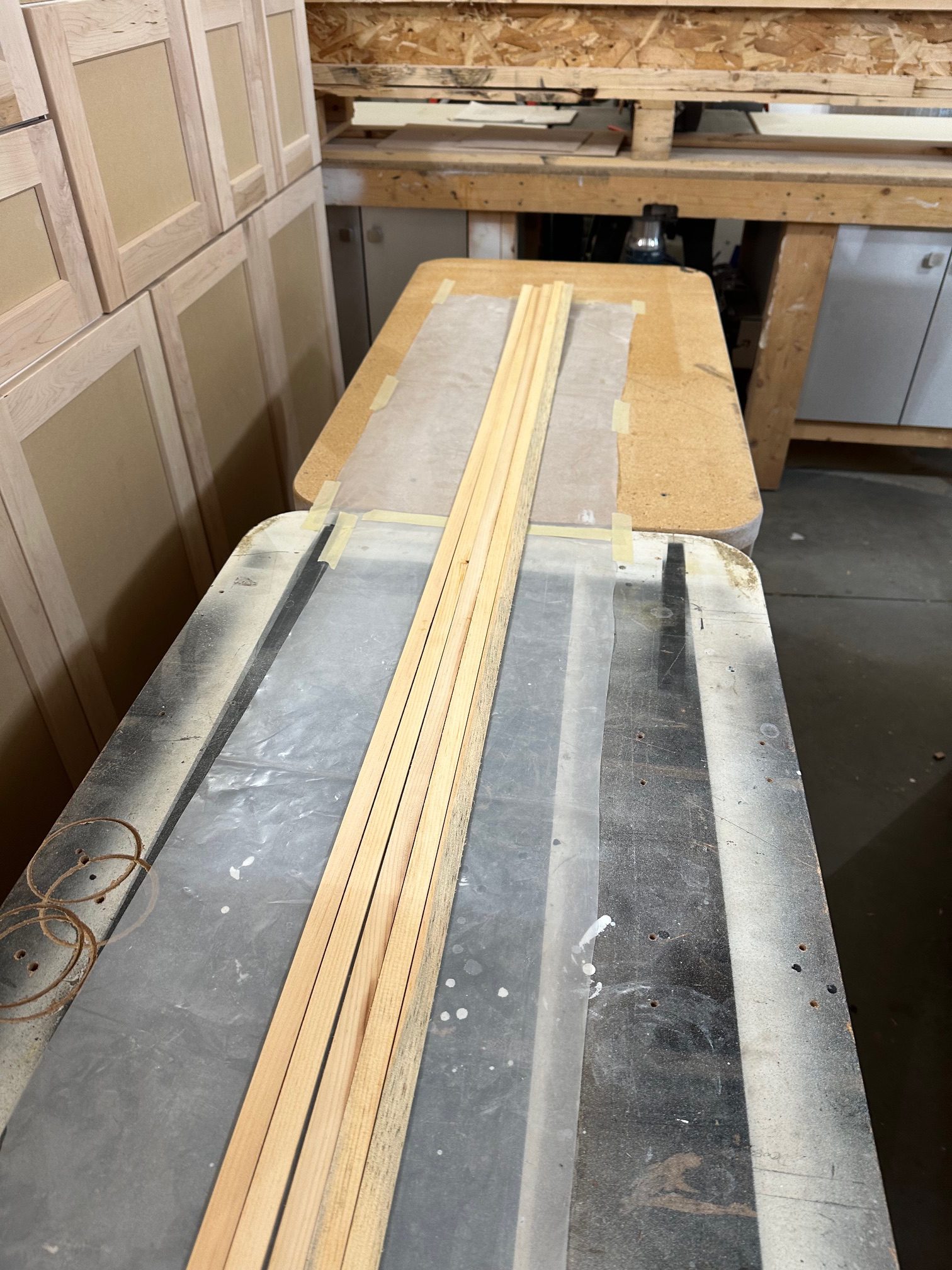
After getting all the screws in place, I wanted to see whether I would need to soak the wood laminating strips to get around the form. I had no trouble whatsoever getting the strips bent around the forms without any soaking, so that was good news. With that bit done, we trimmed 20 of the laminating strips (4 wingtip bows, 5 layers each) down to the right length to clamp down to the forms with a few extra inches on each end. With that done I went home for the night.

Friday morning I was back at it. Mixed up some epoxy in the silicone tray and used the roller to evenly coat 4 of the 5 laminating strips with glue. It worked wonderfully well, I’m glad I bought it. I then just stacked the strips and clamped them to the first form, then repeated the process with the second set of strips. The entire process was so much less complicated than I anticipated — I’m not the least bit worried about repeating it for the other two bows, or for the tail. Of course we’ll see how those bows come off the forms tomorrow…

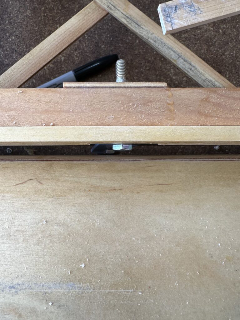
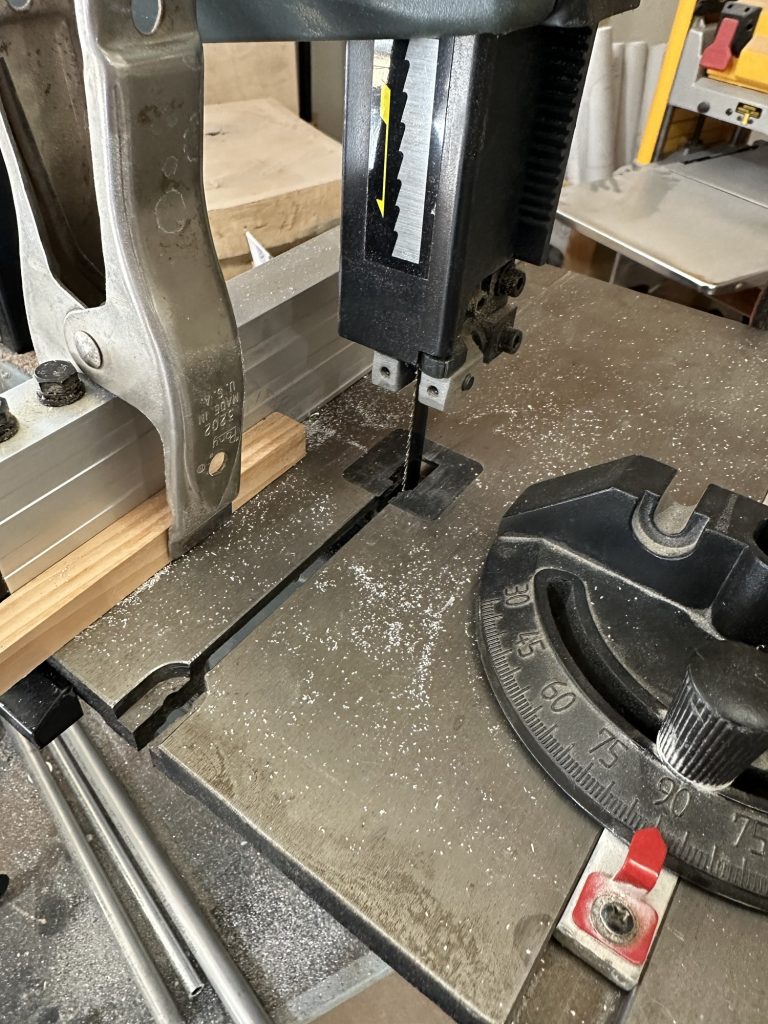
With the bows curing, Stu and I drilled the holes for the bolts and bushings that will attach all of the fittings to the wing spars. Stu’s got a set of Forstner bits, which cut nice clean holes. I’ve got to get a set of those… been meaning to anyway, but that really drove the point home, so to speak. One big advantage is that with the drill press running, you can clearly see the point on the bit to precisely put it right on the mark. Then we cut the 3 degree angle on the lower wing main spar root ends. No pressure at all, just taking a chop saw to a nearly irreplaceable bit of very expensive spruce and aircraft plywood…

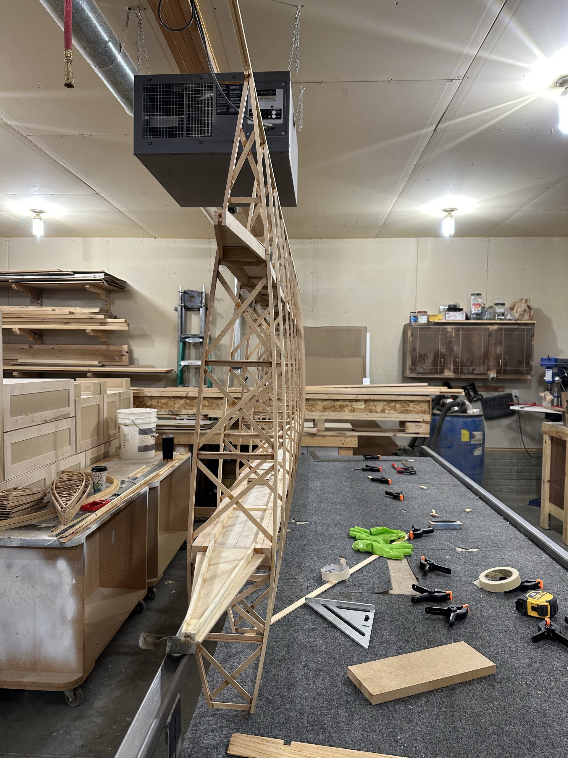
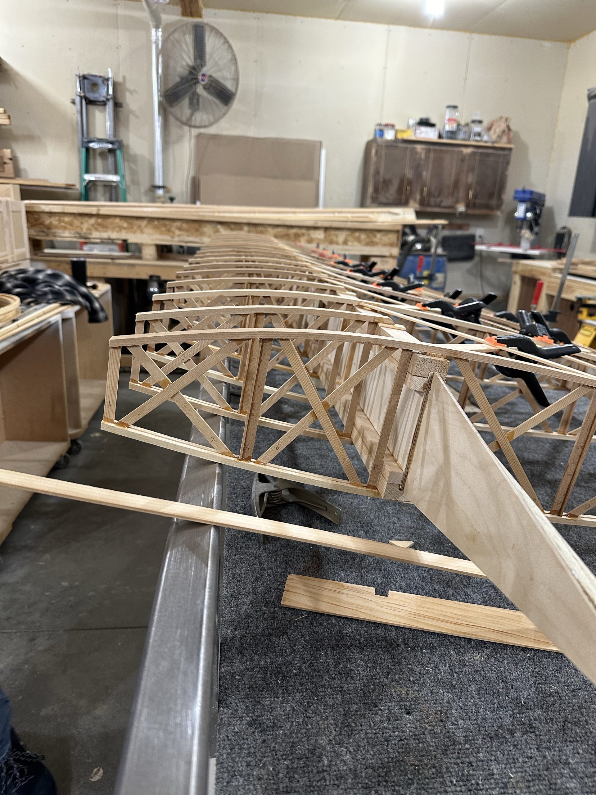
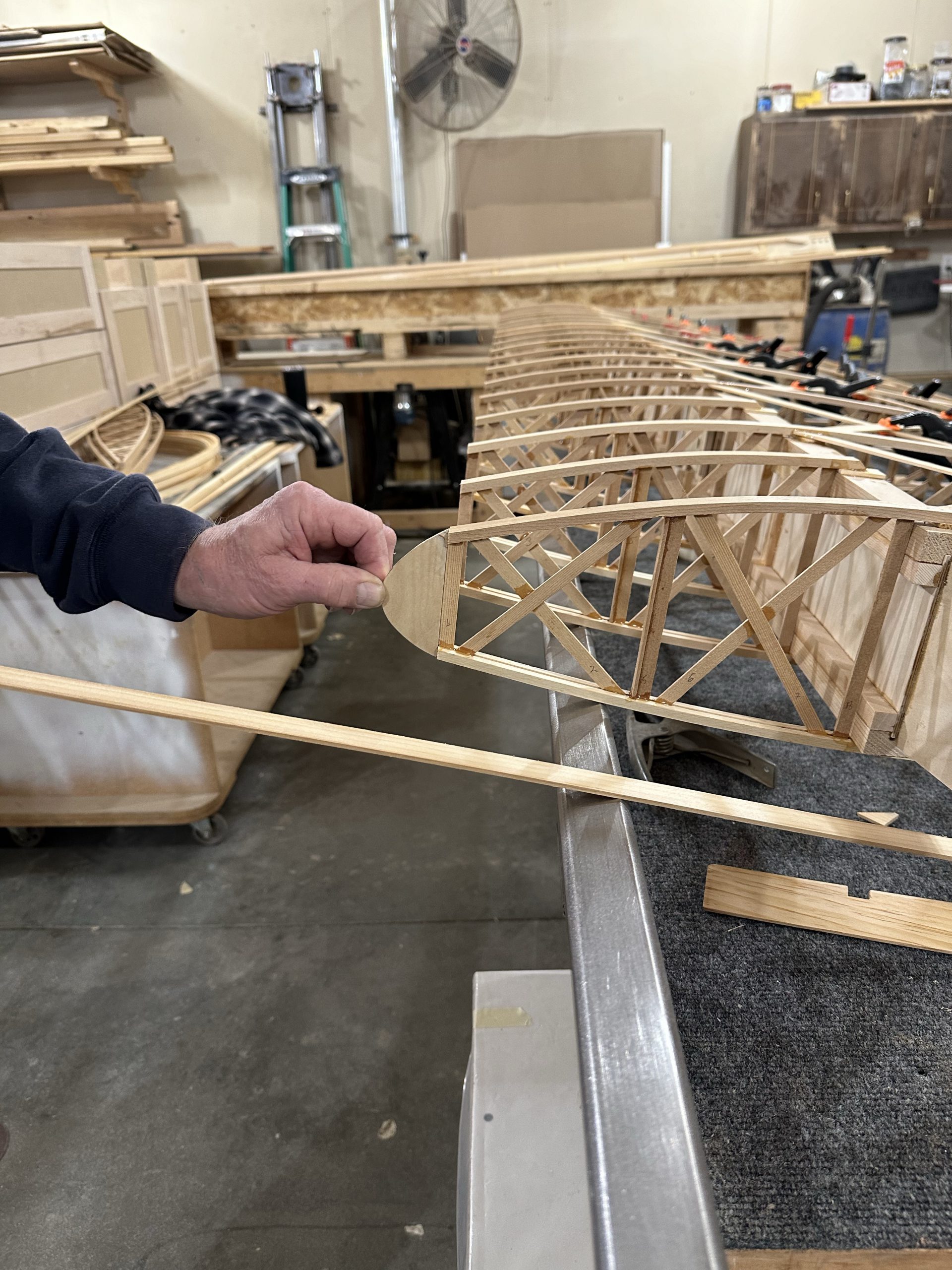
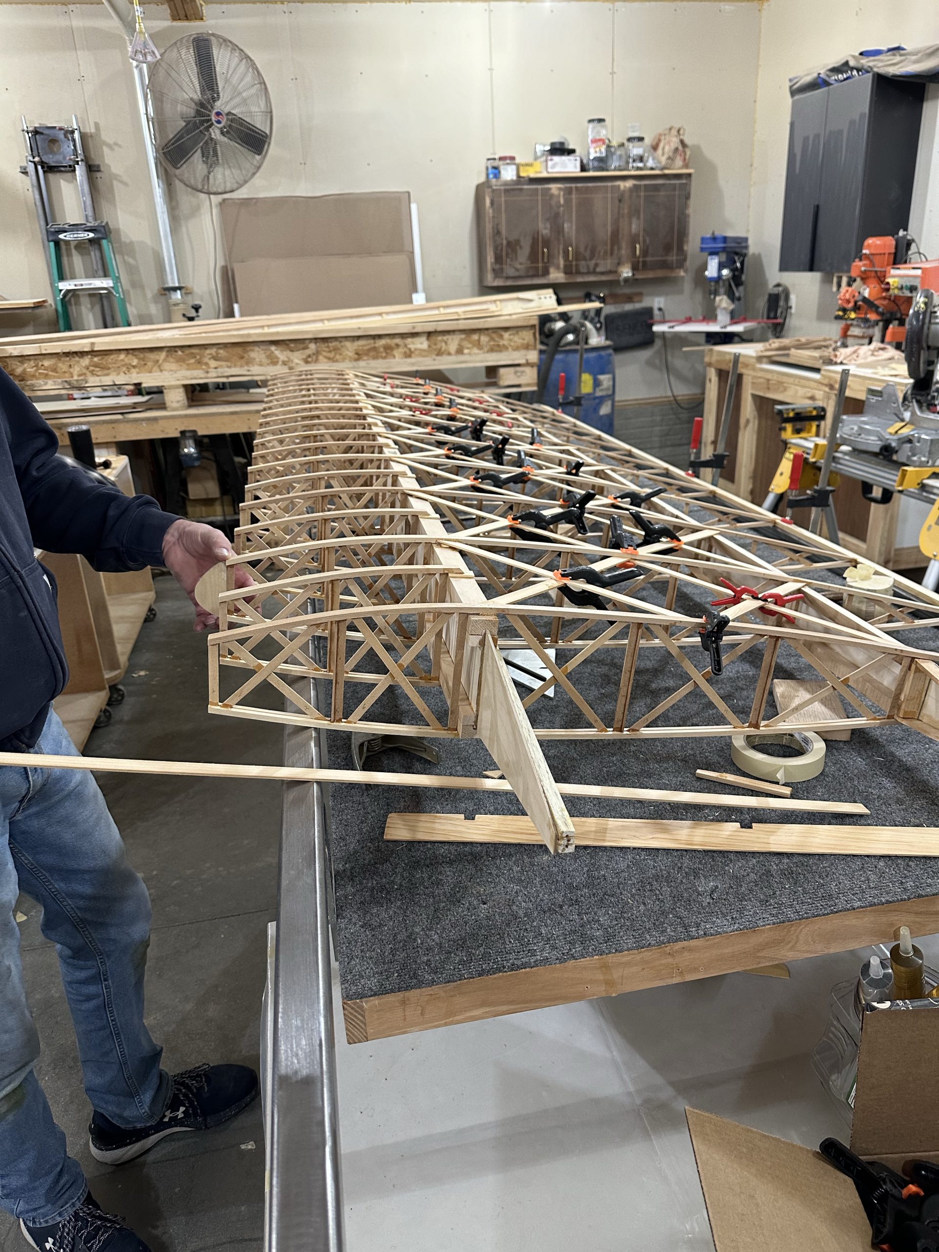
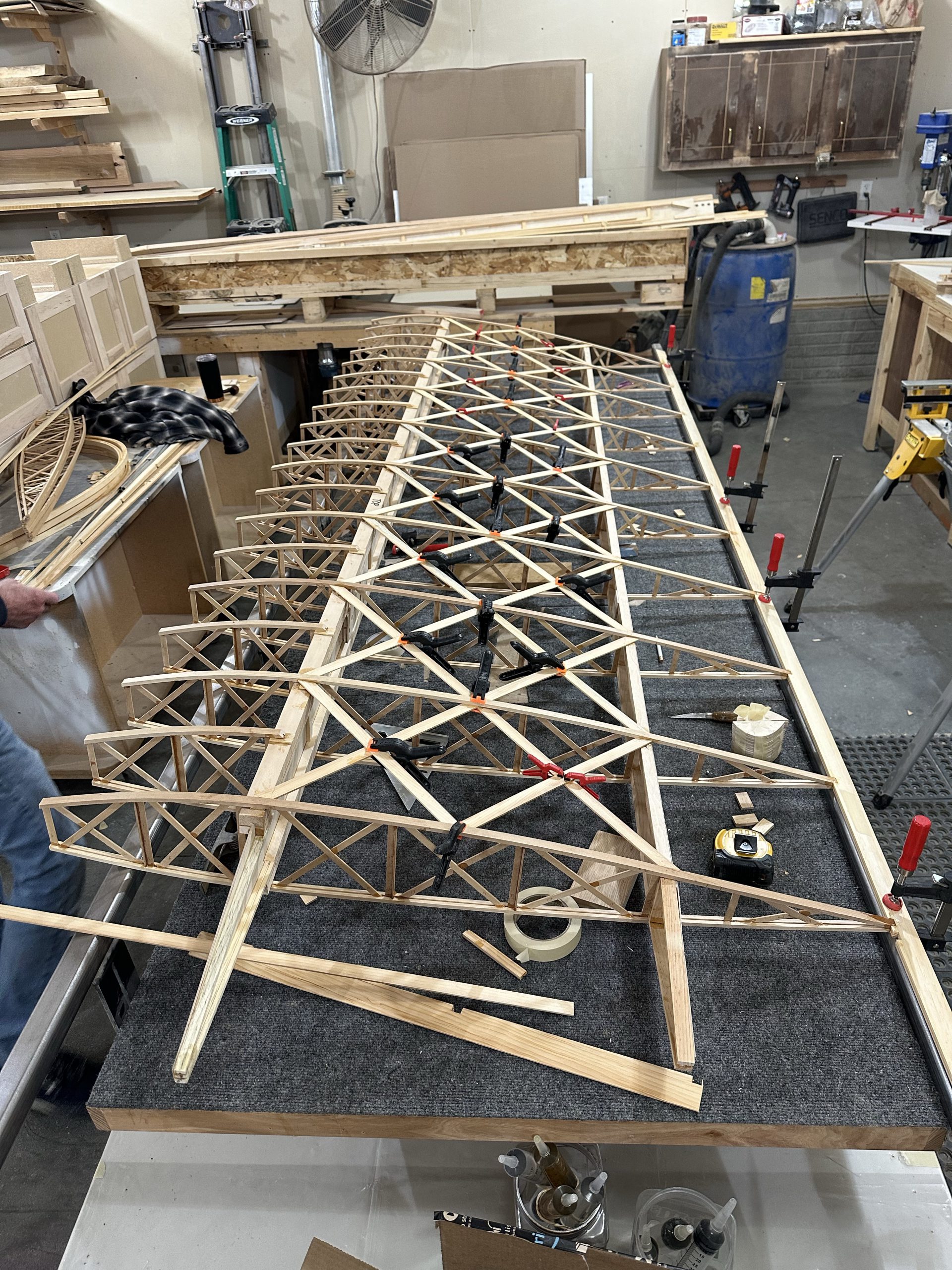
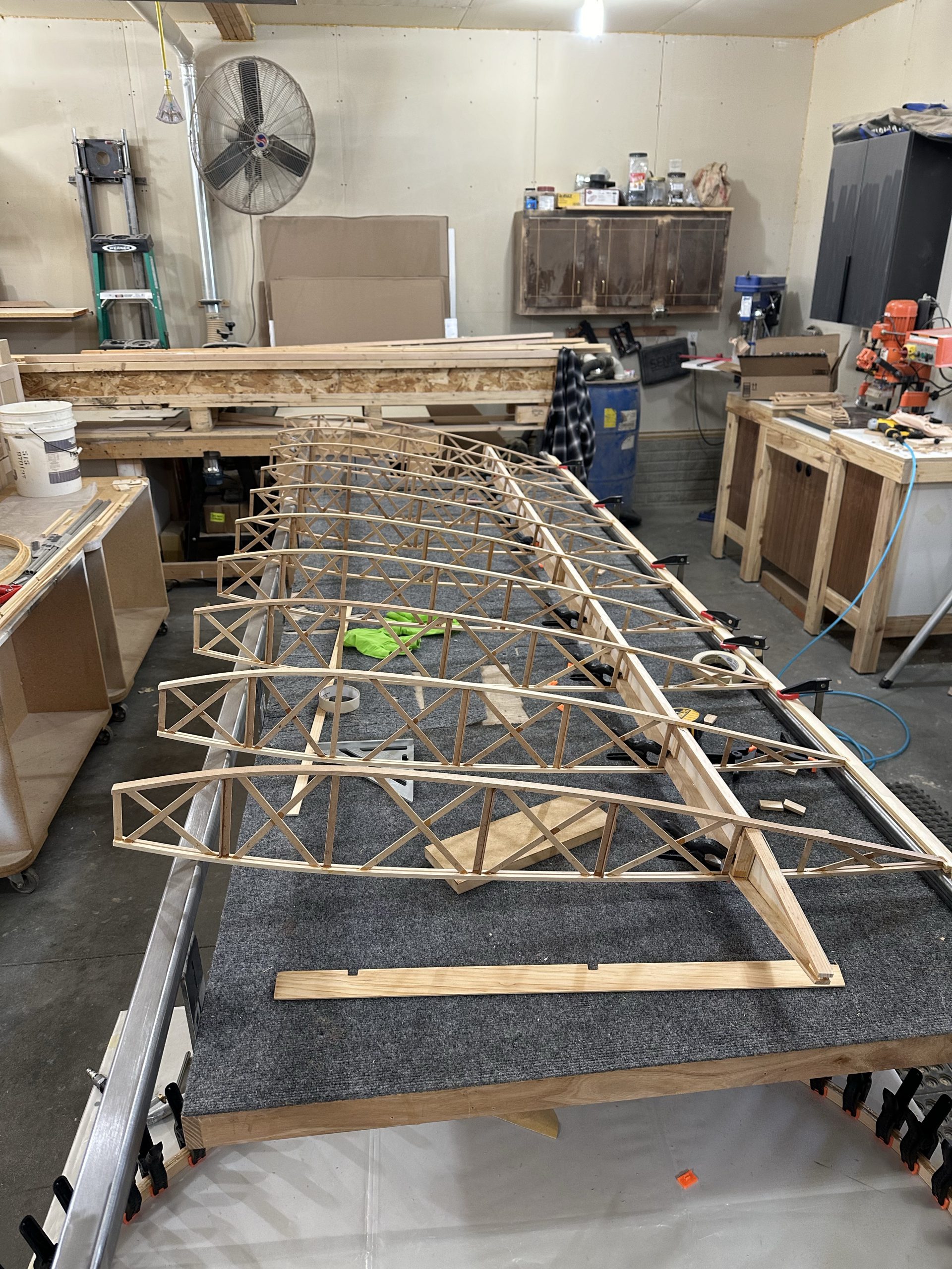
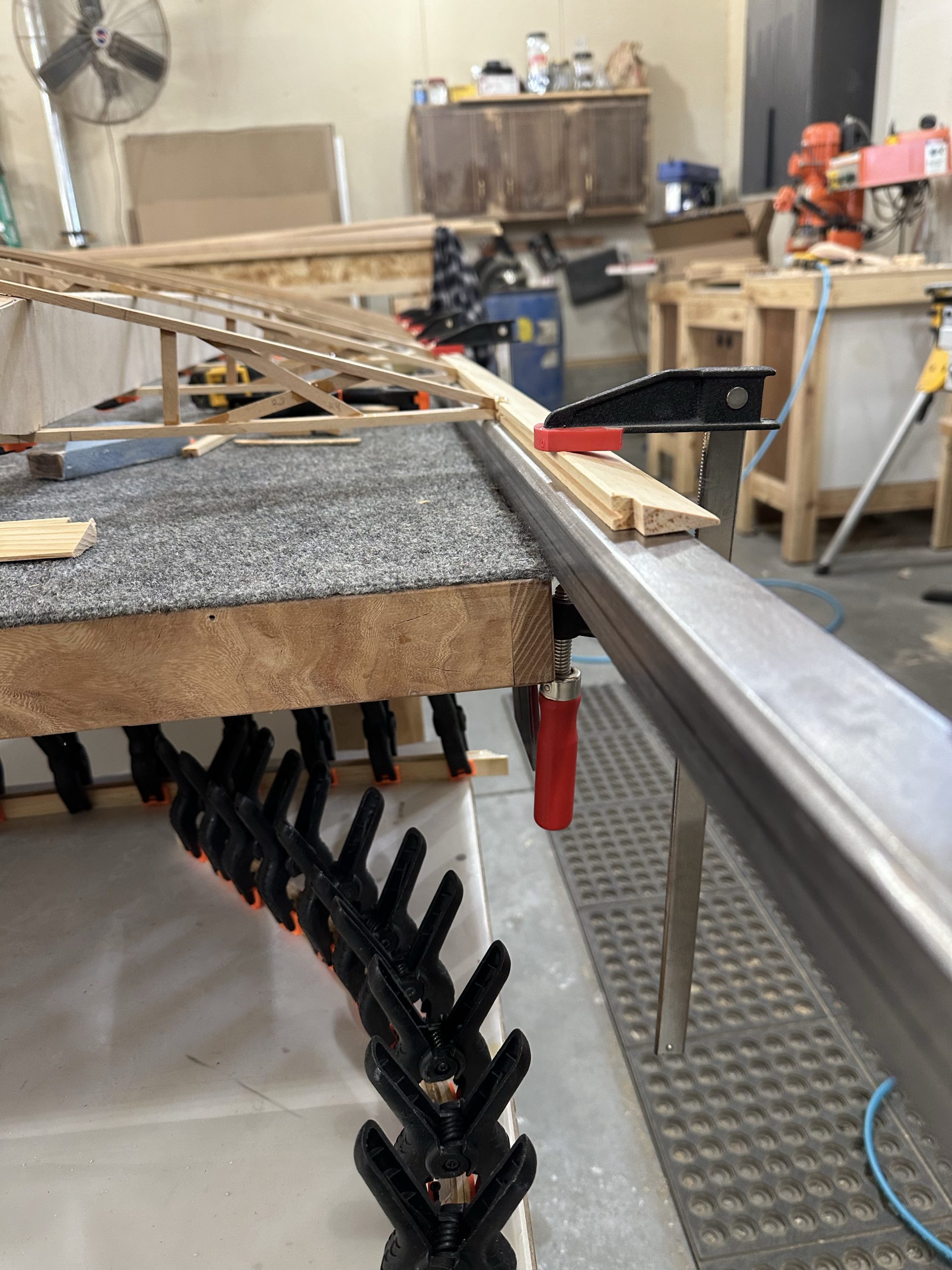
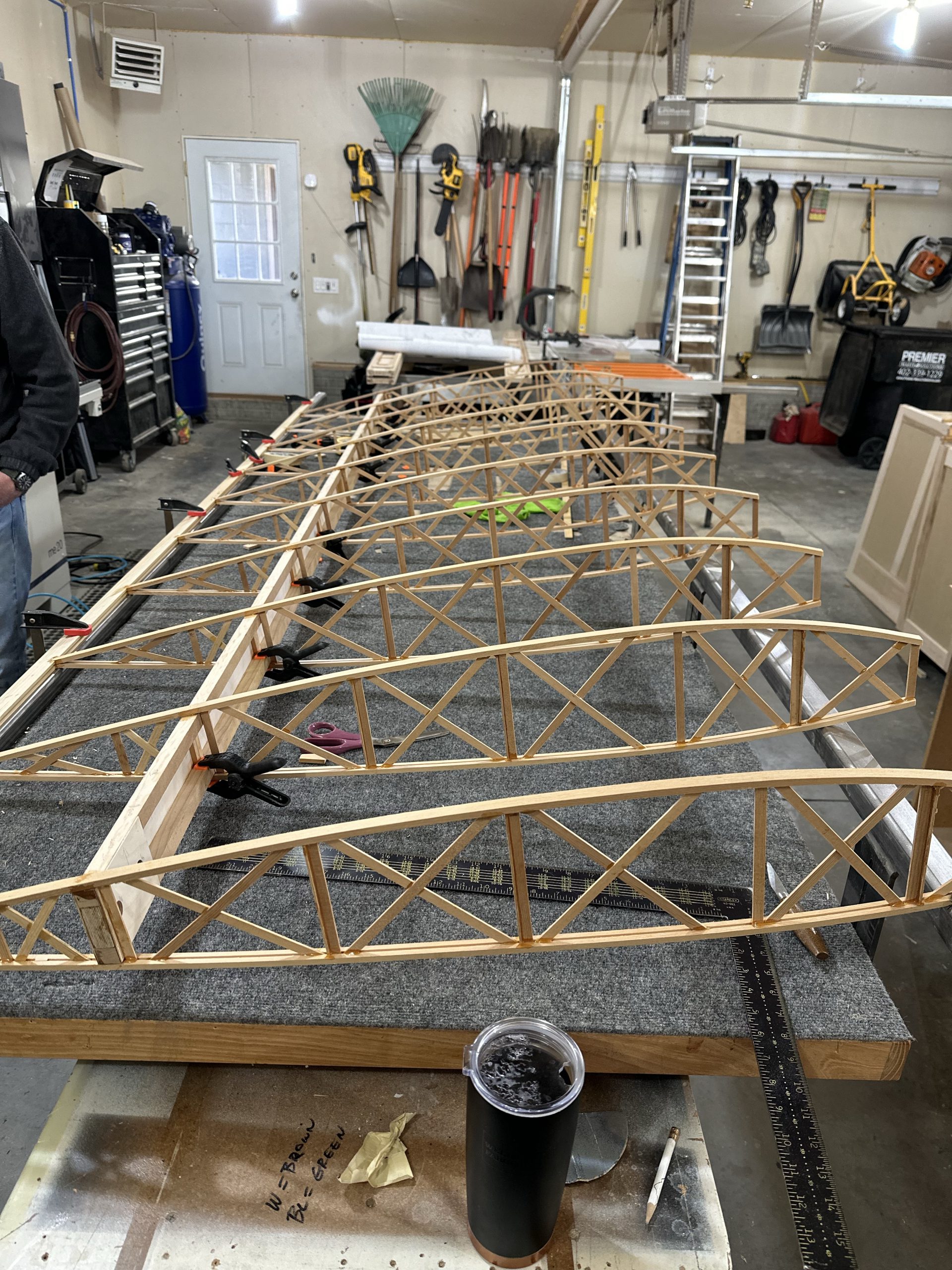
Now it’s time to start actually assembling the wings. We started by attaching a steel rail to the side of the bench to support the leading edge of the ribs. The idea is, rather than supporting the trailing edge material with an angled block to let the ribs sit on the bench tom, we’ll clamp the TE flat to one bar, then use the other to support the leading edge at the proper height to match the angle of the TE. If you’re building one of these, I wouldn’t recommend trying to do it this way without a similar setup. Stu’s got a pair of 12′ long square steel tube rails that bolt to the edges of the bench and can move up or down from slightly above the level of the bench top to about 5-6 inches high. It’s pretty unique. The method outlined in the plans is a solid alternative, though personally if I had to do it without this setup I’d bevel the edge of a long block and use pocket screws to attach it to the bench.

We got the first half dozen ribs in place but were unable to go further, since I had taken all of the aileron ribs back home — I just grabbed the stack of ribs that needed modification, and it didn’t occur to me that the aileron ribs could stay.

So that was today — a lot of progress. By the end of the day tomorrow we should have something that starts to look like an airplane wing, and two more laminated wingtip bows.

11/5/23 updates

Went over this morning to see what remaining tasks I could knock out before starting the first wing assembly, and to do some planning and figuring stuff out — like, how I was going to jig up the trailing edge and other stuff for the wings. Stu came in and had a fantastic idea for using the existing steel rails on his workbench to hold the TE flat and perfectly straight, then supporting the front of the ribs with the other rail. It’s a 10′ bench with 12′ rails, so plenty big enough. It’s a significantly different method than that suggested in the plans, but it’s a pretty unique setup. I’m sure a 2×4 shimmed for the correct angle is a lot easier solution for most people than adjustable 12′ long steel square tube rails. I’m just glad he had them built out of square tube and not round.

Next I gave the main and rear spars a once-over to make sure everything was right. It wasn’t. One of the upper wing main spar tip bow supports was off by 1/2″, the result of not having the two spars oriented the same way when I installed those parts. Or, maybe it was something else. Those supports have been a real pain in the rump, and I have a sneaking feeling I’ll run into issues there again. Anyway, the easiest fix was to cut the offending tip support off with a razor saw, put a slight angle cut on the root end, and re-attach it with appropriate splices. Right now part of the re-assembly is drying; I’m hoping to complete the assembly tonight after the epoxy cures.

I got the ten ribs that I have over there trimmed fore and aft, so they’re ready for assembly. I’m planning to start with the lower left wing, just for the sake of simplicity. The lower right wing gets the wing walk. The two upper wings may or may not get fuel tanks, so I’ll do the lower wings first while I work that out. Therefore the lower left is the simplest and a good place to start, I think.

Stu and I discussed building the wingtip bows. He’s got a 48″ square table with a melamine top. It’s big enough to lay our two bows. I’ll wax it thoroughly and use a glue roller for gluing up the lamination strips. This will be good practice for the tail surfaces, which will need to wait until after the wings are done as they’ll need a 4 x 8 work surface. Now I just need to order a glue roller and about 40 or 50 more spring clamps. Given the size of the stabilizer & elevator assembly, more is better… I’m pretty sure there is no such thing as too many clamps.

Main spar progress

It’s been a busy week. The two upper main spars are essentially complete. Spar caps, stiffeners, and all of the filler and reinforcing blocks are assembled. The only thing not done are the outboard ends, where the tapered pieces for the wingtip bow attachment need to be assembled. The two lower main spars are under construction now. Both have the caps and web glued, and one has the stiffeners on one side. I’m planning to finish as much as I can today on the main spars, and hopefully get at least one of the rear spars glued up.

It’s been a real joy working in a place where there’s plenty of room to work. The availability of a large number of bar clamps – in addition to the 40 or so spring clamps I have – really helps as well. I took the day off work yesterday and was able to get over there once in the morning to set up a spar, then again in the afternoon to take that one off of the jig and glue up the next one.

Stu is anxious to get enough pieces built to start getting wings assembled so they look like wings — I can’t say I’m not in agreement. I was a little tempted to build a rear spar after the first main so we could assemble one complete wing, but I’m convinced that this way is a lot more efficient. For one thing, after the first spar we’ve both figured out enough ways to make the process better that each spar is taking less time than the one before. Just as an example, my process for getting epoxy into the grooves in the main spar caps has evolved and gotten much more efficient with each spar. It’s almost a shame there aren’t any more to do. On the last couple I would get some glue on the long edge of a popsicle stick and use that to spread it into the groove. After doing a foot or so, I’d slowly follow through with an acid brush with the bristles trimmed down to about 1/4″ or so, to make sure it was evenly distributed and get any excess out of the groove. The result was the cleanest glue joints of all the spars.

I’ve been going through T-88 like crazy. Gluing 9 and 10 foot long pieces of wood uses a lot of epoxy, and I know the laminations for the wingtip bows and tail surfaces will use a lot as well. Given the price increases since the last time I bought glue, I think I’ll just order a gallon.