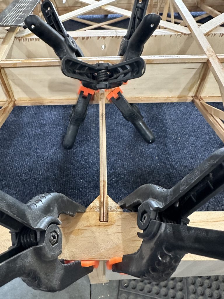
I may be taking too cautious of an approach here, but I really don’t want to have to do a lot of work on the aileron ends like I did on the first one. carefully measured and cut the trailing edge so I could put the CW34 aileron end plates in place. Then, with the CW34s clamped in to make sure the edges lined up with the ends of the aileron spar, I lined up and glued in the pairs of CW35 pieces on each end of the aileron. I have the AL tubing in place to keep everything perfectly aligned.
I’ll probably go back and glue in the CW34s later on tonight. I probably should have just done it this morning. I get a little paranoid about this part of the process, since I’ve had to adjust or re-cut most of the holes for the torque tube.
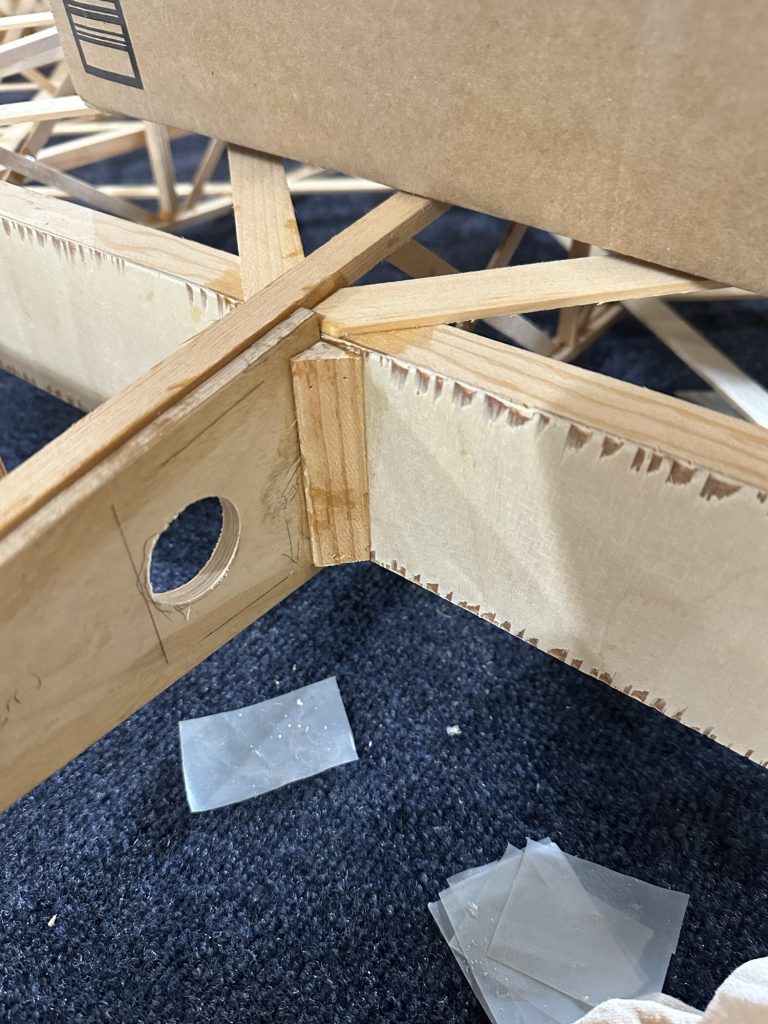
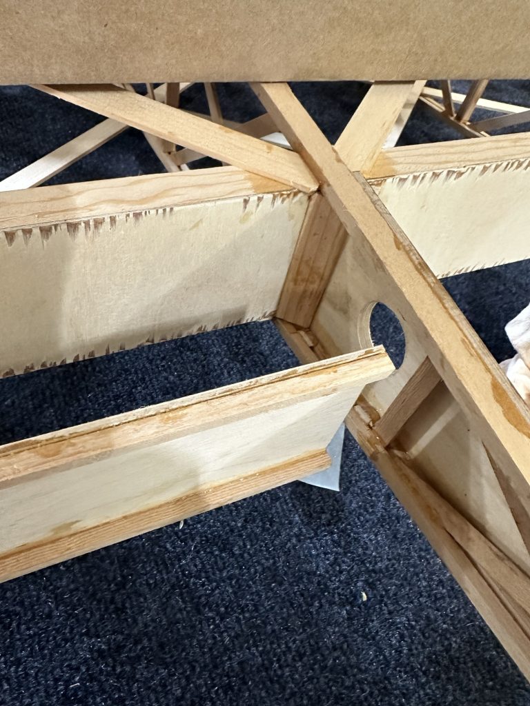
Getting the CW35 aileron nose ribs located perfectly in the aileron is critical to making sure the aileron is straight and consistent with the other wing. Today I slid the torque tube into place and checked the fit of all the pieces that I can at this point. After making some adjustments to the holes in the CW36 end plates, I glued the three CW35s in place in the middle of the aileron. The next step will require cutting the trailing edge to install the aileron end caps, so I want to make sure the torque tube location is easily and consistently reproducible.
I think at this point I may just bolt the torque tube bearings in place (I have a set of 3D printed temporary pieces) and cut the last piece of AL tubing in half. This will let me work with a much shorter and easier to handle piece of tubing while setting up the ailerons.
On the first wing I built, I had the aileron pretty much finished before realizing that I’d left out a bunch of corner blocking. It was a real PITA to add it in after the fact! So this time I paid more attention. Today I cut and glued in all (I think) of the corner blocking for the parts I have done. MUCH easier this way!!
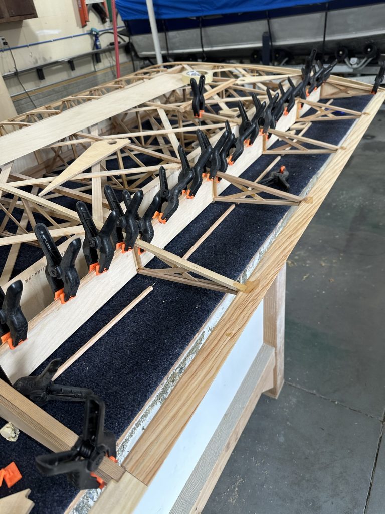
Today I flipped the wing over and got the lower aileron spar caps glued in. I also glued and clamped the CW36 end plates, and a couple of the CW32 aileron nose ribs.
I also drilled the holes in all of the remaining CW32 parts. I may need to cut a couple more of those; it looks like I’ll come up short for the upper wings. I’ll check the crate to see if they got loose and are hiding somewhere, but it’s not a big deal – I have the plywood to make them.
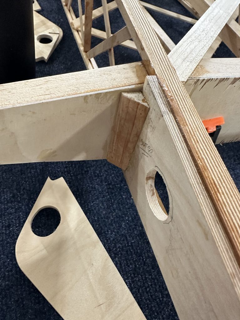
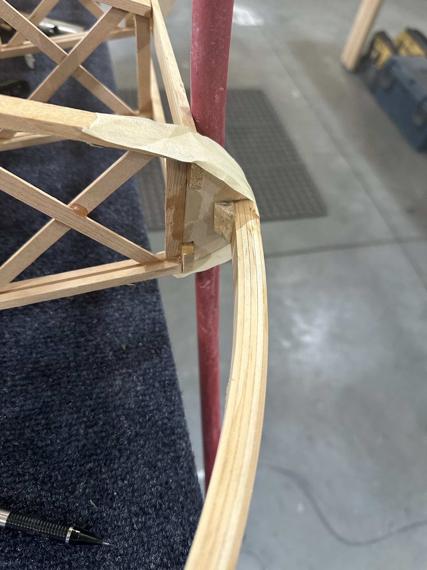
Today I got the aileron spar web cut and glued in, along with the top pieces of 1/4″ spar cap. I couldn’t get to the bottom side to clamp those pieces without some significant effort, so I left those for the next session. I also got the CW32 pieces cut and sanded to fit between the rib caps. I trimmed and clamped the CW36 and CW34 pieces in place to locate the aileron torque tube, then marked the CW32 pieces for the holes that will need to be drilled for the torque tube.
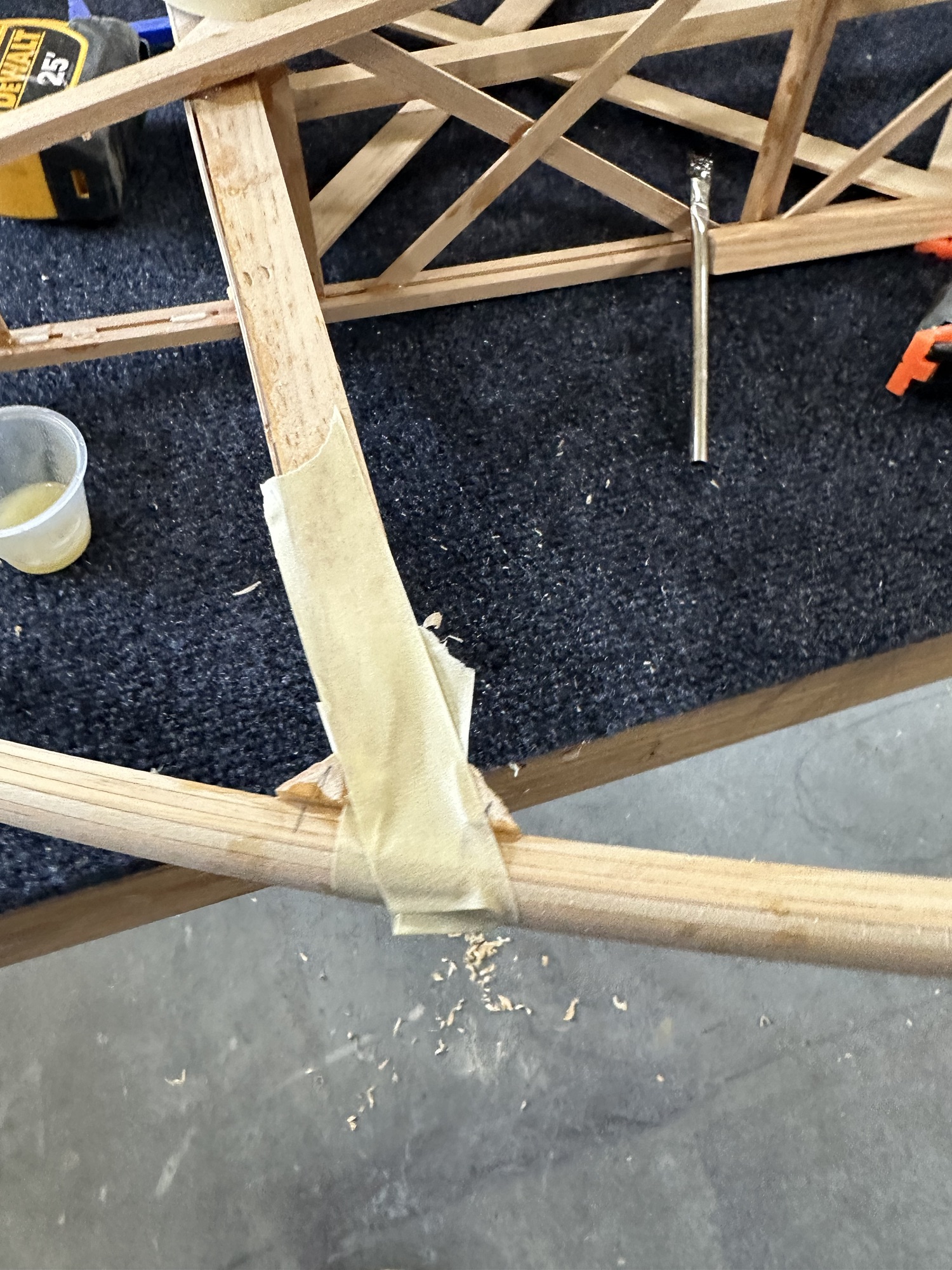
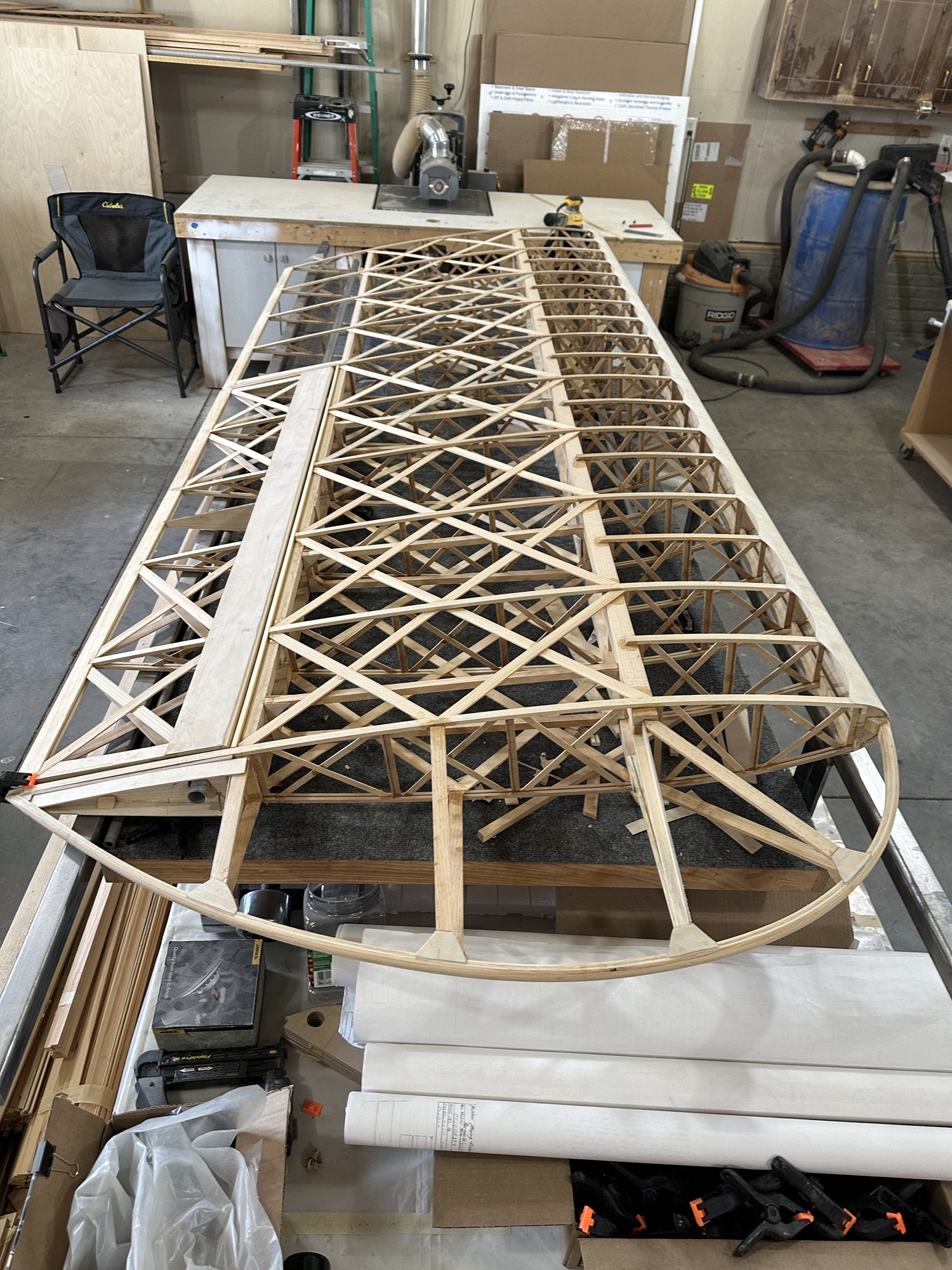
The wingtip is nice and solidly in place, so now I just need to sand the blocking and trailing edge flush so I can start installing the gussets and additional bracing.
This time around I plan to NOT screw up the same way I did the first aileron, by assuming that the holes in ANY of the parts are drilled in the proper place. As I did before, I’ll index everything off of the CW34 parts, using those to locate the torque tube, and drill or sand everything else to match them. And of course I’ve already 3D printed a pair of torque tube bearing blocks for this wing. The final parts will be milled out of UHMW or something similar, not 3D printed, but these are great for getting all the holes located without the risk of messing up a flight part.
The more I use it, the more I like my little razor plane. This thing was bought back in the 70s, I think, by my father for use on R/C airplanes that we (mostly he) built in our basement, usually from scratch. It’s a plastic body with a blade that resembled a heavy duty, oversized razor blade. The key thing I found was to use light passes, and hold the plane at an angle to the wood. It’s quite effective for shaving down spruce, plywood, and even the odd bit of end grain. It’s usually quicker than sanding.
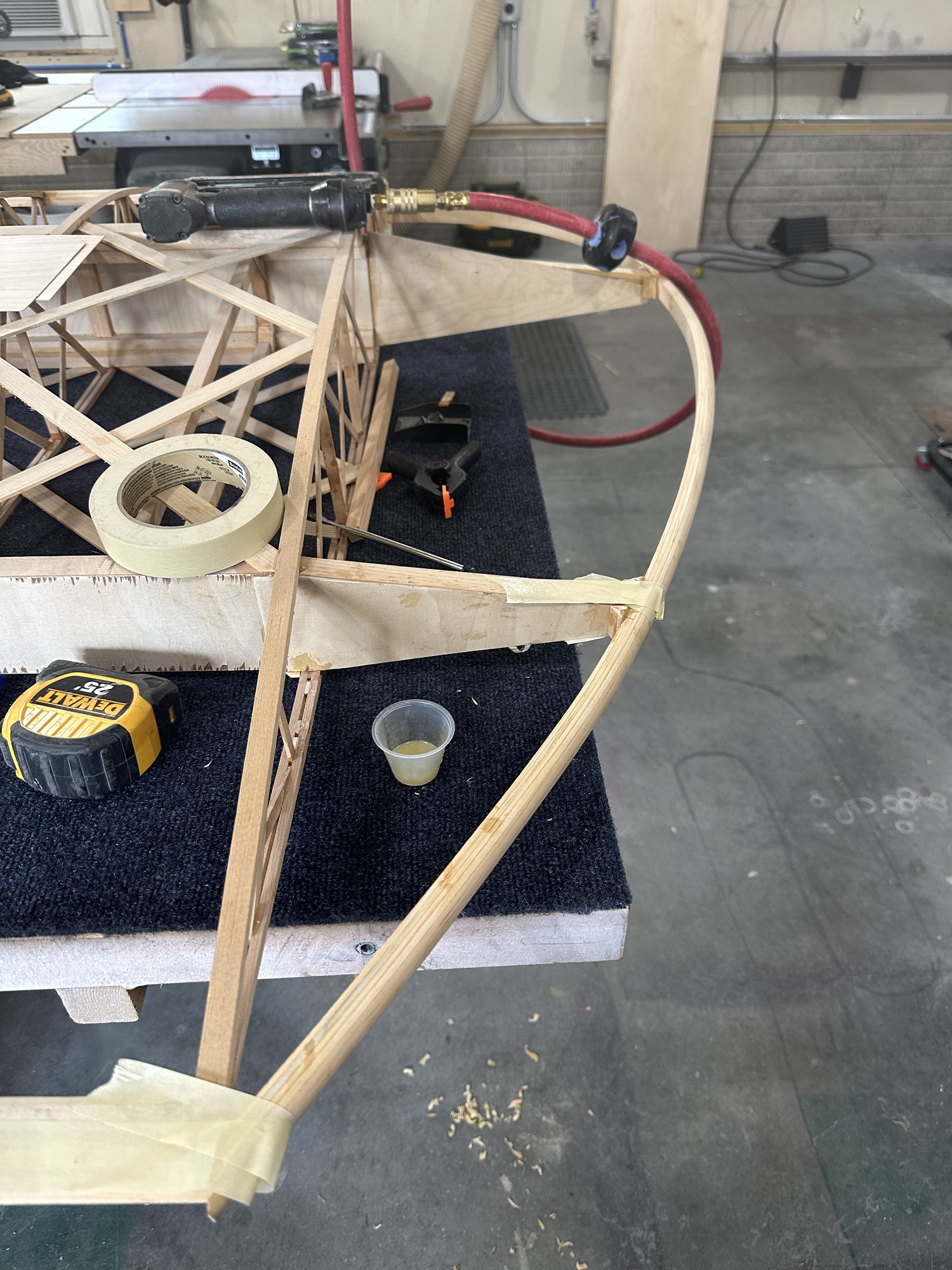
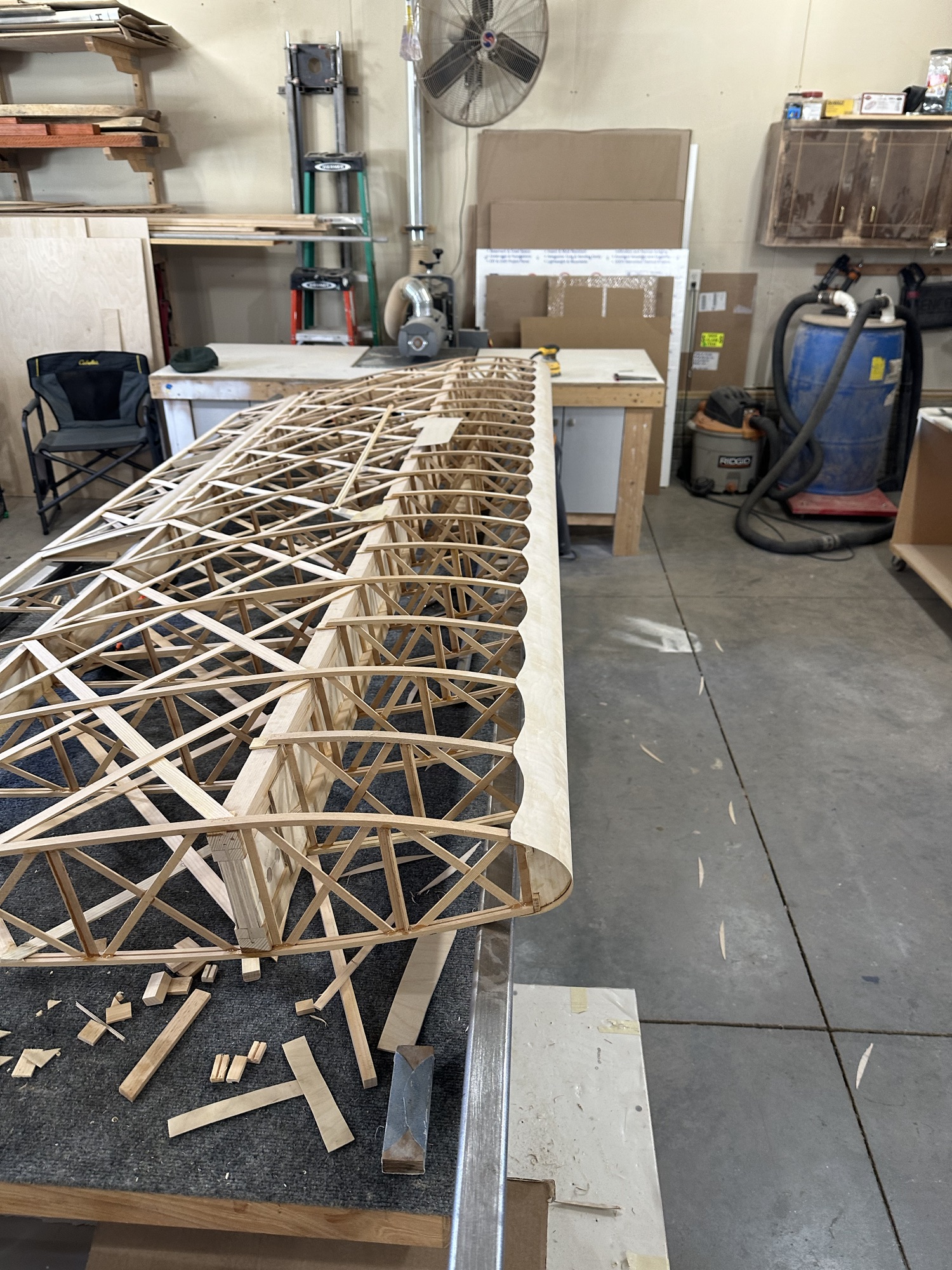
Today I got the end nose rib notched and the wingtip glued in place. I have the blocking at the spar tips and nose rib, but will still need to block and shape the trailing edge as well as gluing in the plywood gussets. Still, it feels good to have the wingtip on. It looks more like a wing!
I also trimmed the CW36 pieces. These go on the ribs just outside the aileron bay and hold the torque tube support bushings. As supplied they were about 3/8 too long for the inboard side, and 7/16 for the outboard side where there’s an additional thickness of plywood where the wingtip spar web overlaps. For this I just set the miter gauge on the table saw to match the angle of the piece, then set the table saw to cut off the length needed. I won’t glue those two pieces in place until after I have the rest of the aileron structure built up.
Today came and went without mixing up any glue. I sorted out the nose plywood, then went through all of the aileron pieces and got them cleaned up, marked, and re-taped for the three remaining ailerons. I got the aileron spar web and marked it for the notches to clear the ribs, then brought it home and started cutting those notches on the bandsaw. I pulled a wingtip bow down and checked its fit; it looks like minimal trimming will be needed.
I also collected all of the aluminum pieces I had at Stu’s shop and brought them home, and cut the ends on the bandsaw. They’re all CAW2 pieces, I think — I need to dig out the rest of the pieces and get them all drilled and finished off. I’ll finish them on the belt sander and Scotchbrite wheel before priming them. My little 3D printed guide button worked great for this. I don’t recall if I described it or not, but it’s just a 1″ diameter by 1/8 thick disk, with a 1/4″ diameter by 1/8 thick nub in the center. Put the little piece in a 1/4 bolt hole, and the larger piece gives you a perfect guide for shaping the end of the bracket with a 1/2″ radius. They’re disposable if you nick or break one, and only take a little while to print up. I’ll probably print a few more in case I destroy any while using the belt sander.
I spent some time trying to determine whether the wing walk pieces will be of any use to me or not. The plan sheet and plywood supports all seem to be made for some earlier version of the wing. The notches on the supports don’t work (or even come close to working) with the root blocks on the main spar or rear spar. The forward plywood bits are too long, and even if cut off don’t match the curve of the wing ribs. There are supposed to be three installed forward of the spar — but that would only work if I removed one of the false ribs. I still don’t know what I’ll do for the wing walk. I do know that 1/4 plywood for the rear portion would need some curve in it, and I’m not sure about that. The plan notes say to nail it in place until the glue dries… ::shrug:: This is why I’m considering a laminated layup with some wood and maybe a layer or two of carbon fiber.
Mostly small things over the past week. I cut and installed some more corner blocking that I didn’t get done before, tested a couple new iterations of the bearing block/spacer, and fine tuned the aileron to the opening. Along the way I’ve noted a few new lessons learned…
Never trust the plans, or the supplemental sheets included with them. They’re often inaccurate. Like the AL bracket diagrams that call out 3/16″ holes when they will get 1/4″ AN4 bolts… and on and on.
Get the torque tubes in place, holes moved or enlarged where needed, and bearing blocks in place and holes drilled beforecutting the ailerons from the wing. Otherwise it’s just a bitch getting everything aligned after the fact to locate the bearing blocks. This of course goes along with correcting all of the many problems with the holes that are pre-drilled in those plywood parts.
Make sure all of the corner blocking is installed around the aileron bay as early as possible, and certainly before installing the CW40 plywood stiffeners, aileron leading edge skin, and so on.
Go over the plan sheet more often and in greater detail to make sure I don’t miss anything that will be a pain to install later on… like corner blocking that would be much easier to plane or sand to shape than to try to cut to match odd angles.
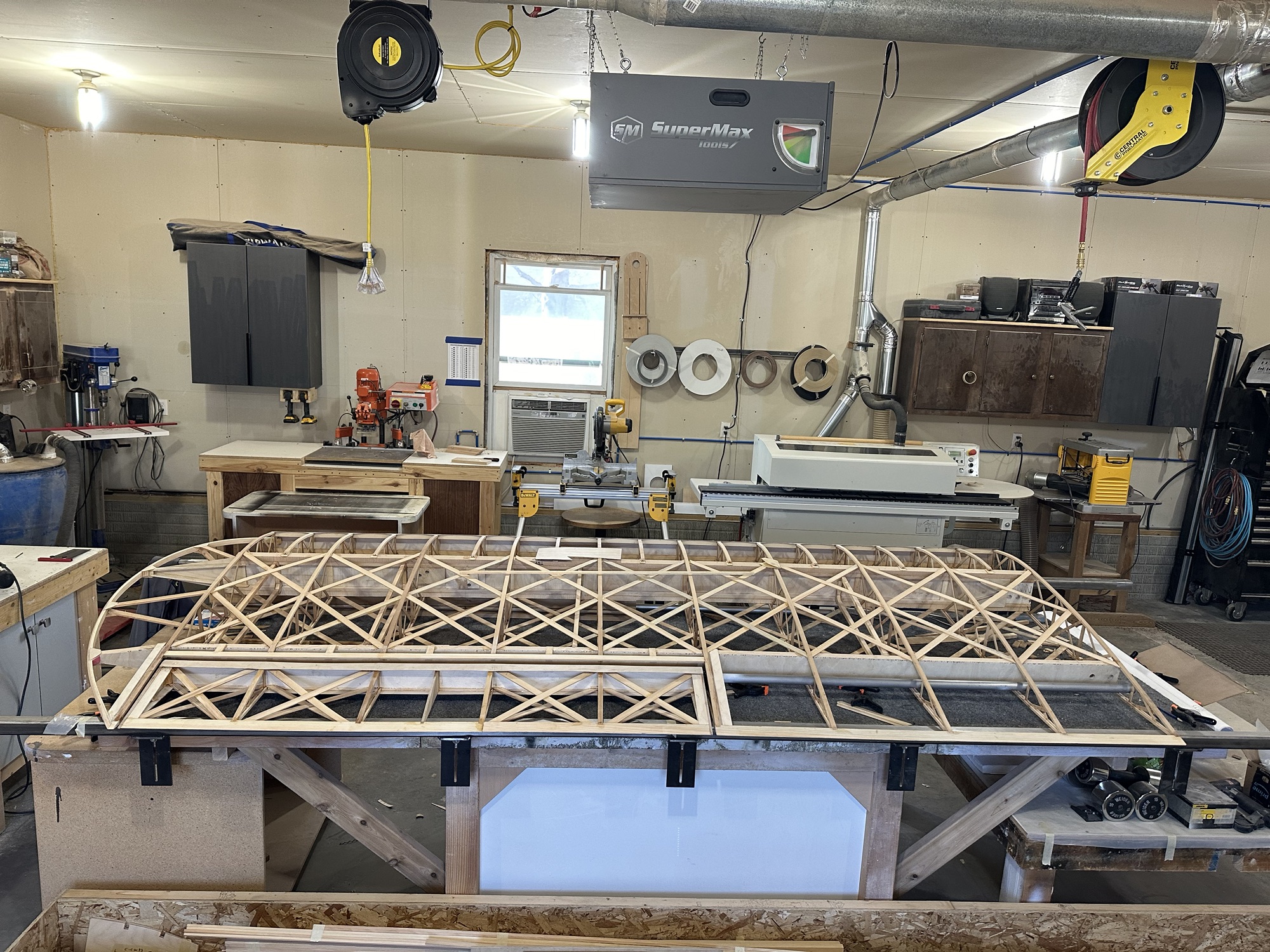
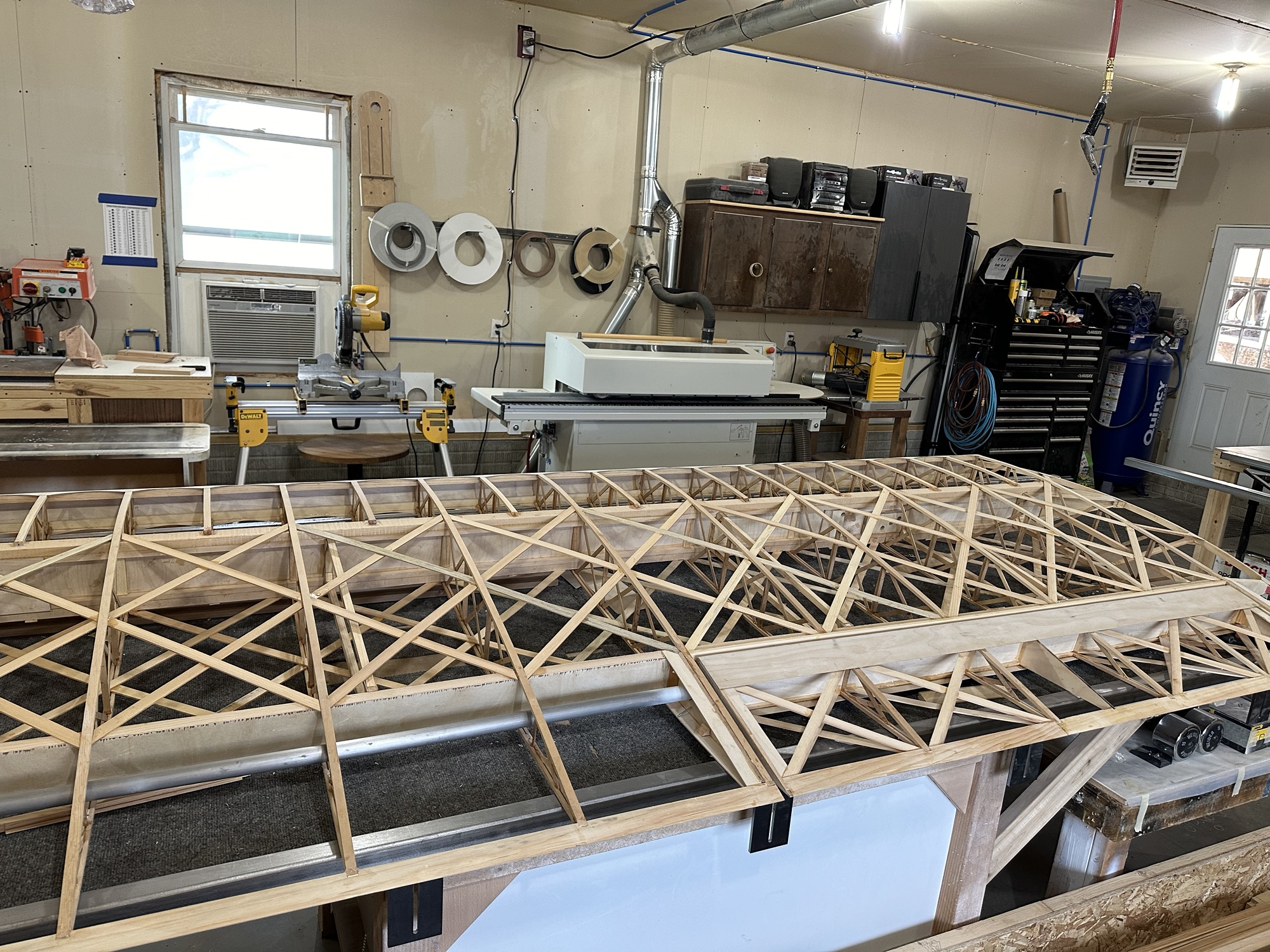
Install the compression struts before the geodetics! That cost a couple hours of added time working through tight openings.
Not necessarily a “lesson learned”, but something I’d like to explore. All of the ribs ended up needing a 1/8 shim between the top rib cap and the main spar. Rather than shim them with separate pieces, I want to see if I can maybe cut and install the geodetics at the same time the ribs are glued, or something. Or possibly just use temporary shims, and glue the top cap to the spar as the geodetics are installed. It could lead to neater and better construction.
Top and bottom leading edge plywood has been scalloped. That wasn’t as big a chore as I thought it would be. We used a thin stainless scale to establish a curve between each pair of ribs, marked along it with a pencil, and cut the wood with a utility knife. Some cleanup with sandpaper and Bob’s your uncle.
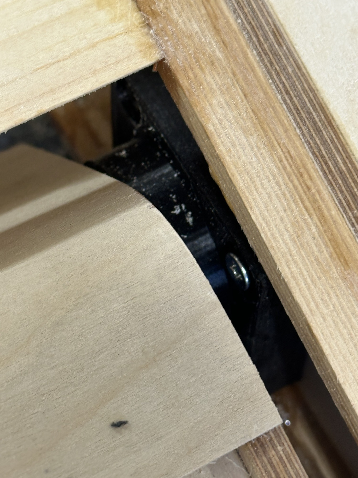
I’ve made a few iterations of the bearing block. Today I’ll print a couple more test pieces and I think I’ll be done. They fit great, the aileron is very well located, all in all I think it’s a lot more precise than a piece of plywood and a chunk of PVC pipe.
I’ve been preparing some of the wing attachment fittings. I have one or two of each part drilled with 1/8 pilot holes; I’ll use those to match drill the rest, then enlarge the holes for the AN4 bolts. The biggest question was hot wo round off the ends. For that I drilled a 1/8 hole exactly 1/2 inch from the disk on my disc/belt sander. Now I can use the tail end of a drill bit as a pivot pin and put a nice radius on the end of the fitting. I’m glad I kept my gray Scotch-Brite wheel on the bench polisher; it makes quick work of cleaning up the ends of the AL bars.
Yesterday (2/16) I cut and glued in some corner blocking I had missed on each end of the aileron and the ends of the aileron bay. Lesson learned: that would have been a lot easier had I done it before the geodetic bits and plywood stiffeners had been installed.
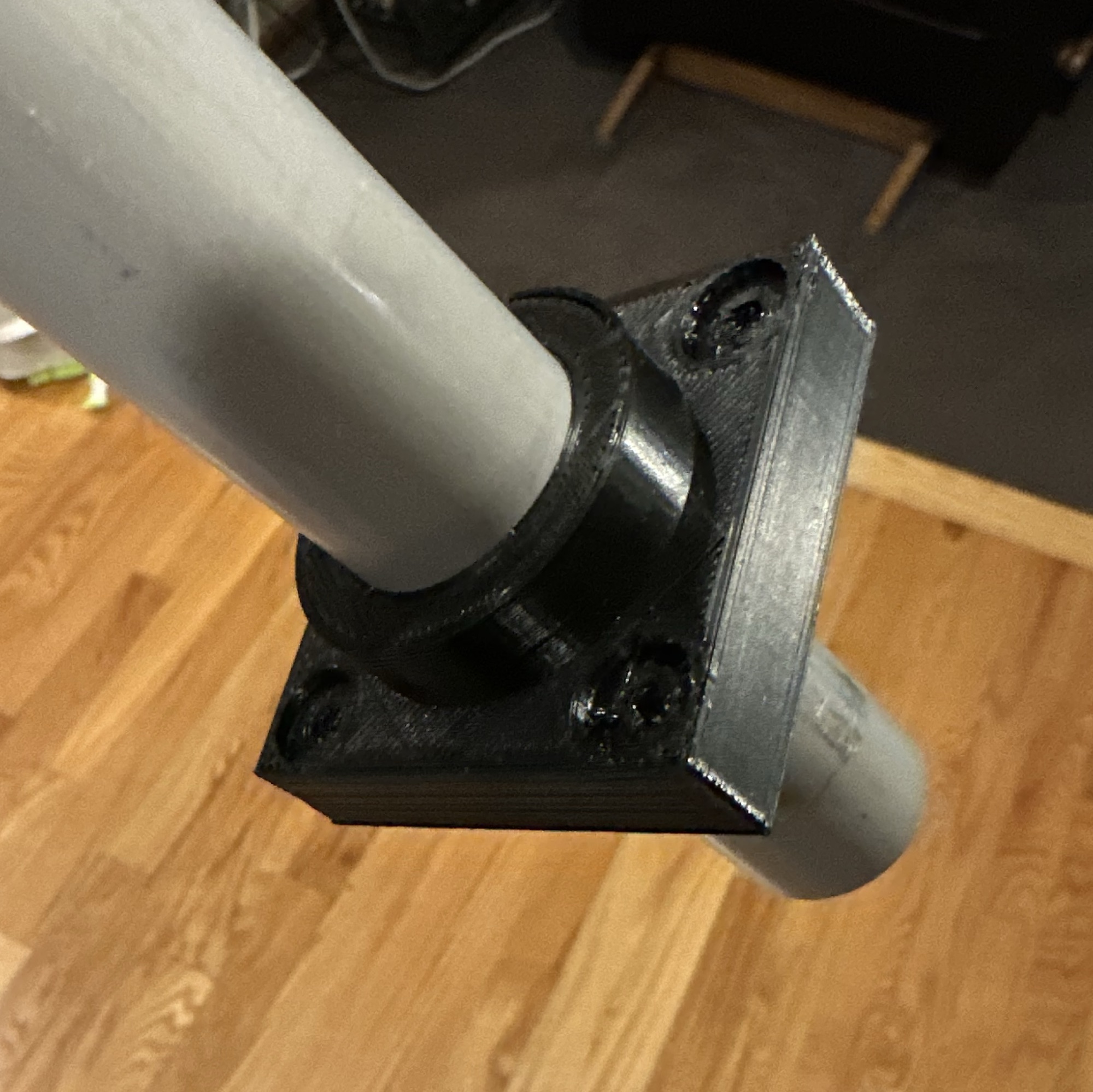
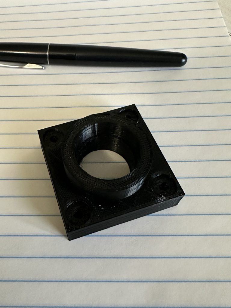
I’m getting to the point where I kind of need the torque tube bearing blocks installed. Then there are the 3/8” spacers, which the plans call out as pieces of PVC pipe. I figure, since I’m going to CNC machine the bearing blocks anyway, why not just make those and the spacers one piece? I pulled up the design in OpenSCAD and added the spacer. I gave it a slightly larger ID than the bearing block so it doesn’t add drag to the aileron control. I 3D printed a couple samples to use for fit & function testing. If that goes as expected I’ll get a chunk of 1” UHMW and pass the design file to Stu for machining. I’d planned to use some 1/2” UHMW I have for the bearing blocks, but I’ll keep that for now and use it for something else.
3D printed test part. It’s difficult to see but there’s a step in the bore for the torque tube.