Aileron spar and parts fitting

Today I got the aileron spar web cut and glued in, along with the top pieces of 1/4″ spar cap. I couldn’t get to the bottom side to clamp those pieces without some significant effort, so I left those for the next session. I also got the CW32 pieces cut and sanded to fit between the rib caps. I trimmed and clamped the CW36 and CW34 pieces in place to locate the aileron torque tube, then marked the CW32 pieces for the holes that will need to be drilled for the torque tube.

The wingtip is nice and solidly in place, so now I just need to sand the blocking and trailing edge flush so I can start installing the gussets and additional bracing.

This time around I plan to NOT screw up the same way I did the first aileron, by assuming that the holes in ANY of the parts are drilled in the proper place. As I did before, I’ll index everything off of the CW34 parts, using those to locate the torque tube, and drill or sand everything else to match them. And of course I’ve already 3D printed a pair of torque tube bearing blocks for this wing. The final parts will be milled out of UHMW or something similar, not 3D printed, but these are great for getting all the holes located without the risk of messing up a flight part.

The more I use it, the more I like my little razor plane. This thing was bought back in the 70s, I think, by my father for use on R/C airplanes that we (mostly he) built in our basement, usually from scratch. It’s a plastic body with a blade that resembled a heavy duty, oversized razor blade. The key thing I found was to use light passes, and hold the plane at an angle to the wood. It’s quite effective for shaving down spruce, plywood, and even the odd bit of end grain. It’s usually quicker than sanding.

CAW2 brackets

Over the past couple of days I’ve gotten all 14 of the CAW2 brackets shaped. I had drilled all of them already, but the ends needed to be rounded off. One end of each will be hidden inside the wing, but some will have one end exposed so I wanted them looking decent.

I designed a radius guide to help with the bandsaw and sander. It’s just a 1″ diameter disk, with a short 1/4″ button on the center of one face. Stick the button into the hole on one end of the bracket, and the guide is there to show a 1/2″ radius all the way around. My original idea was to use them to scribe a line to follow when finishing the ends. I had 3D printed a couple of them, and found it was just as easy to just leave it in place and work around the edge. Inevitably, of course, you end up nicking one so I printed up a batch of 9 more. I used 3 of them to finish off the CAW2 brackets.

Given that there are a bunch of other brackets to finish, I’ll definitely try the scribed line approach as well. Overall, though, I’m pleased with the results. I used the bandsaw to lop off the corners, then shaped the ends with a disc sander and finished them on a Scotch-Brite wheel. I had planned to paint them, but I may not. I’ve still got a batch of metal etch and Alodine (Bonderite 1201, to be precise), so if it still works I’d like to just give them a conversion coating that weighs nothing; that way they are protected from corrosion but only the exposed parts get paint. I’ll probably try a test piece to see if the Alodine still works; if not, I’ll get some self-etching primer and use that instead.

Wing down, new bandsaw blades

Wednesday afternoon I went over and worked with Stu to get the wing down off the rack and onto the bench. I grabbed the nose ribs and, since they weren’t cut out for the false spars, took them home with me. Before I did, I carefully marked where they need to be notched.

Stu has gotten out of the cabinet business and has sold off much of his wood shop equipment. The thickness planer, jointer, band saw, edge banding machine, and some other stuff is gone. Wait — the band saw is gone? Crap, if I’d known I’d have bought it from him on condition that I could leave it where it was. Oh well. I have one at home, a cheap little 10″ tabletop model.

While cutting the notches in the nose ribs, it was immediately apparent that the saw blade was toast. I’d wanted to replace it anyway, as it’s a 1/4″ wide blade and not really great for keeping a straight line. I removed and measured it, then tossed that and the equally worn out metal blade I had for it that couldn’t make it through 1/8″ 6061. I ordered a 62″ x 3/8″ x 6 TPI wood blade, a 10 TPI wood blade, and a 1/2″ wide 24 tooth metal cutting blade.

A few days’ delay was inserted here, while dealing with another issue unrelated to the airplane..

The blades arrived over the past few days. I put the 6-tooth wood cutting blade on and got the saw adjusted’ it works great. I can cut a 1/16 slice off the end of a 2×2. I think I still need to get the saw table squared up a little better with the blade before trying to do any re-sawing, but it’s close enough for the time being. The metal cutting blade slides through that 6061 like butter, so I’ll be able to finish off the AL fittings for the wing and get the tubing cut for the bushings. Then I can order the bolts I need and get the fittings installed.

Returning to work

It’s been a bit since my last update here. In the past couple of weeks we took a nice cruise vacation, and I developed a pretty severe case of bronchitis. It’s possible these two things are not unrelated; one of the risks you take to get a little Caribbean sun and salt air in the middle of winter, I guess!

I’ve been working to get the leading edge of the aileron wrapped with plywood. Honestly, at this point I can understand how someone would make the decision to scrap an aileron and start from scratch. I don’t think I’ll go quite that far, but there have been challenges. I’m adding to my “lessons learned” for the next three ailerons, that’s for sure. Part of it is just developing a process to get the ply to wrap over the pretty sharply curved top surface. This part I solved with a couple pieces of Styrofoam and some dumbbells, to effectively clamp the aileron to the bench with the ply trapped underneath. That should hopefully take care of the upper portion. The bottom edge of the top piece of ply isn’t yet glued to the structure, so I’ll have to figure that out today.

I’m really looking forward to building the next wing. I’ve learned so much while building this one that I’m pretty sure the next will take a lot less time, although I’ll have to figure out the wing walk on the next one. I talked to a guy building an RS-80 Tiger Moth the other day. He told me about improvements he’s made to his wing walk to avoid seeing the wing deflect when someone steps onto it. I’m not sure how much I’ll be able to do on mine, but he’s using carbon fiber in a substantial number of places on his build. Honestly, the wing walk is one area where I was thinking I would need to beef things up a little anyway… if you’ve met me you’ll understand why.

But, of course the devil is in the details. Every time I think I’m almost finished with this wing I am reminded of all the detail work that has yet to be done. I need to cut and install all of the bushings for the bolts; finish cutting, shaping, and drilling the various aluminum mounting brackets; cut and finish the scallops in the leading edge plywood; figure out and build the transition from leading edge to wingtip bow (most likely foam)… there’s a lot of stuff left to do, but fortunately it’s really only a few days’ work.

Cold weather musings

Haven’t done much on the plane for a few days now. We have been in the grips of a winter storm, followed by a cold snap. We got several inches of snow; anywhere from a couple inches in the front yard to maybe 2′ drifts closer in to the house. The temps throughout the 3-day weekend never got above -7, and the wind was blowing. This is not weather conducive to going outside for anything non-essential.

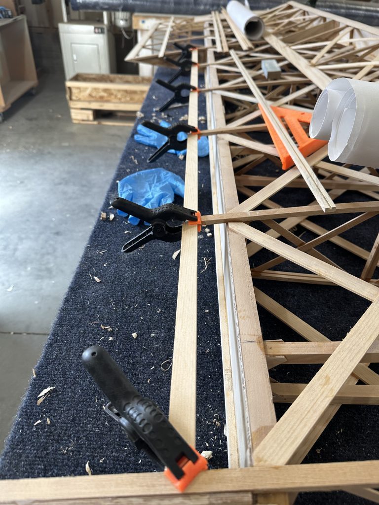
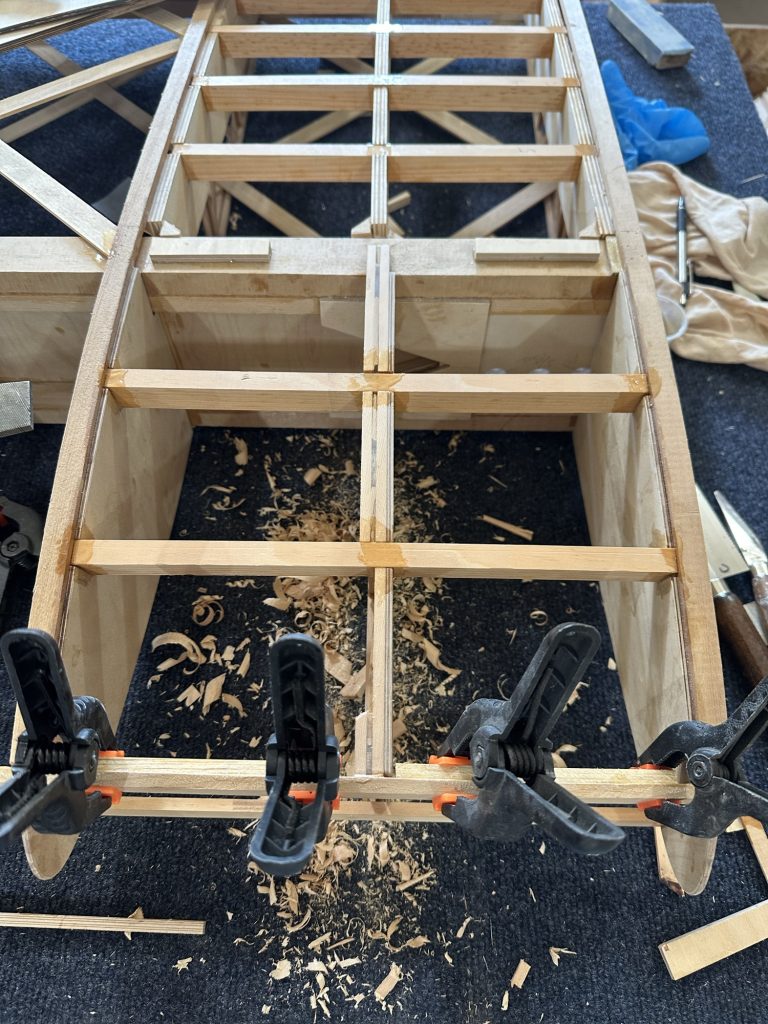
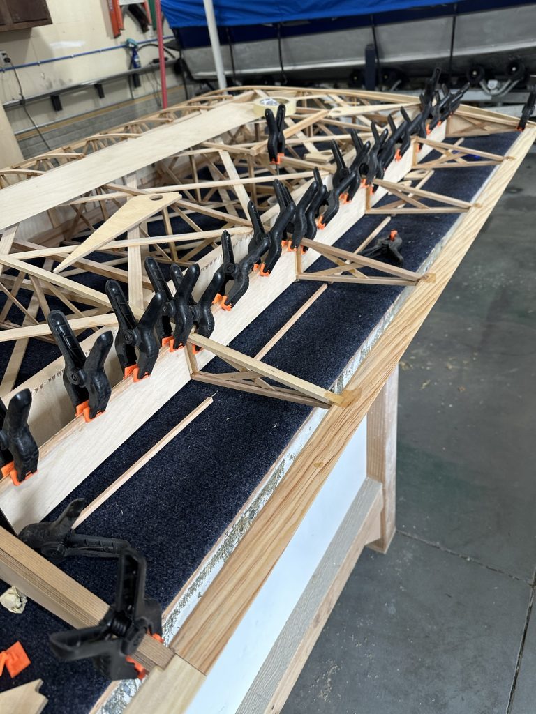
During the last build session, I tried cutting a few of the bushings needed for the wing. The results were not great. While a chop saw will go through and make a beautiful clean cut, it will also randomly launch the cut-off piece somewhere in the shop, often with a nice big chunk out of the end. Not what I was after! I did get one bushing cut successfully, and another done after much filing to get it down to its final size.

After doing some research, I believe I’ll end up building a band saw sled to cut the bushings. I can make it with a nice end stop to cut the tubing to consistent lengths, and it should make it relatively easy to get an acceptably square cut. I’m hoping the cut ends turn out clean enough to dress with a brief time with some sandpaper.

The bloody compass is still very slowly seeping fluid. I suspect the face plate is not perfectly flat. I think for now I’ll leave it, but at some point I’ll need to drain, disassemble, and maybe use a thin coating of Aviation Form-A-Gasket on the black rubber seal. At least everything works well, it looks great, and the LED light is quite effective. I have no idea why I’ve invested so much work into a mag compass, to be perfectly honest… but it’s been an entertaining project. I just like restoring old things.

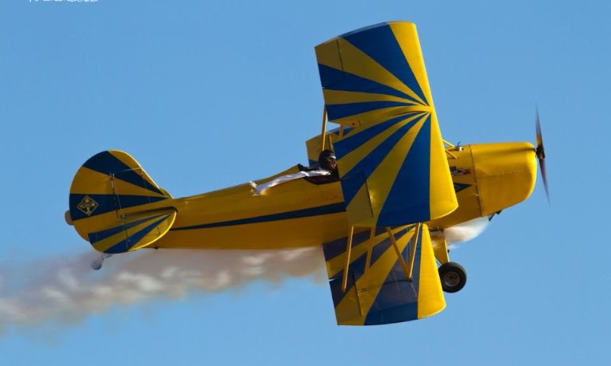
I’ve had no success at all getting answers out of “CKD.aero” regarding the pricing and availability of parts and subkits for the Celebrity. I’ve been trying to get pricing for the wing tanks so I know whether to plan on using them or not. It just feels like Fisher got bought by people who have no clue what to do with it. The website has been stripped of any pricing or availability information. It took me weeks to get anyone to even respond to an email, and despite a couple of promises I have yet to get a useful response from anyone. I guess I’m on my own. It’s a shame, but I did decide to build from plans; I think I’ll be able to muddle through.

More aileron work

With a week or so off in there due to both my wife and I having COVID, things have been progressing. I got one of the torque tubes measured and cut for the wing. The plywood bits for the nose of the aileron ribs all got drilled out. Looking at how to do the aileron build brought up some issues, though. The plans say to glue and clamp those in place — the challenge is in how to do that, exactly. The clamping anyway.

In order to make the job a bit less complicated, I glued up the plywood sandwiches for the two ends and the middle, where the locking pins will install. I spread some epoxy and threaded the pieces onto the cutoff piece of torque tube to get them all perfectly aligned – and they were tight. With everything aligned perfectly, I shot a few 1/2″ 23 ga. micro pins to keep everything stable, then added spring clamps and took them off the tube so they wouldn’t end up glued to it.

Next day I ran those and the 1/8″ ply pieces on a spindle sander with a 3/4″ drum on it to enlarge the holes a bit. I wanted a slip fit on the tube for the thicker pieces, and a more “roomy” fit for the 1/8″ pieces. Those were supposed to get 1-1/8″ holes in the first place, but I missed that part in the instructions and we drilled them to 1″.

Realizing that the wing now can’t sit flat on the steel rail due to the trailing edge of the wingtip bow not being tapered to match the wing, I took care of that as well. Only the last couple inches of the bow need to be tapered. I started with a little razor plane that Dad used for model airplane work to shave the bow lamination and corner block down very close to the contour I wanted. I then finished it up with a sanding block, and I’m quite happy with the result.

Everything is ready now to get the plywood pieces glued into place. I’d have done it today, but as I was about to mix up the glue I was reminded that it was time to go pick up the grandkids, which turned into dinner and a late arrival home.

Building the Wingtip Bows – and more

It’s really nice working in Stu’s shop with lots of room and plenty of work surfaces. One of those work surfaces is a 48″ square low table, with a 3/4″ melamine laminate top. It’s just the size needed for laying out thew wingtip bows. I started out by laying a large piece of cardboard out and taping the plans page over it. Then I used a sharp punch to poke through each of the nail locations on the plans to mark on the cardboard where they should be. Since I wanted to get two bows done at a time, I then rotated the plans page and marked a second set of nail locations.

Rather than hammer nails into the tabletop, we taped some poly sheet and then the cardboard down onto the surface and drilled 1/16 pilot holes. Stu has a bunch of trim head screws, so we sunk those using a block of wood as a depth gauge so that the heads are just above the 3/4″ mark – since we’re laying down 3/4″ lamination strips. With all the screws in place we pulled off the cardboard, leaving the poly sheet and screws.

Knowing that I’d need to spread a lot of epoxy in a short amount of time, I bought a small silicone glue roller and tray. The tray is about 6″ long by 3″ wide, and the roller is a bit under 2″ wide and is grooved to hold more glue. Since it’s all silicone rubber, the cured epoxy just pops right off after use.

After getting all the screws in place, I wanted to see whether I would need to soak the wood laminating strips to get around the form. I had no trouble whatsoever getting the strips bent around the forms without any soaking, so that was good news. With that bit done, we trimmed 20 of the laminating strips (4 wingtip bows, 5 layers each) down to the right length to clamp down to the forms with a few extra inches on each end. With that done I went home for the night.

Friday morning I was back at it. Mixed up some epoxy in the silicone tray and used the roller to evenly coat 4 of the 5 laminating strips with glue. It worked wonderfully well, I’m glad I bought it. I then just stacked the strips and clamped them to the first form, then repeated the process with the second set of strips. The entire process was so much less complicated than I anticipated — I’m not the least bit worried about repeating it for the other two bows, or for the tail. Of course we’ll see how those bows come off the forms tomorrow…

With the bows curing, Stu and I drilled the holes for the bolts and bushings that will attach all of the fittings to the wing spars. Stu’s got a set of Forstner bits, which cut nice clean holes. I’ve got to get a set of those… been meaning to anyway, but that really drove the point home, so to speak. One big advantage is that with the drill press running, you can clearly see the point on the bit to precisely put it right on the mark. Then we cut the 3 degree angle on the lower wing main spar root ends. No pressure at all, just taking a chop saw to a nearly irreplaceable bit of very expensive spruce and aircraft plywood…

Now it’s time to start actually assembling the wings. We started by attaching a steel rail to the side of the bench to support the leading edge of the ribs. The idea is, rather than supporting the trailing edge material with an angled block to let the ribs sit on the bench tom, we’ll clamp the TE flat to one bar, then use the other to support the leading edge at the proper height to match the angle of the TE. If you’re building one of these, I wouldn’t recommend trying to do it this way without a similar setup. Stu’s got a pair of 12′ long square steel tube rails that bolt to the edges of the bench and can move up or down from slightly above the level of the bench top to about 5-6 inches high. It’s pretty unique. The method outlined in the plans is a solid alternative, though personally if I had to do it without this setup I’d bevel the edge of a long block and use pocket screws to attach it to the bench.

We got the first half dozen ribs in place but were unable to go further, since I had taken all of the aileron ribs back home — I just grabbed the stack of ribs that needed modification, and it didn’t occur to me that the aileron ribs could stay.

So that was today — a lot of progress. By the end of the day tomorrow we should have something that starts to look like an airplane wing, and two more laminated wingtip bows.

11/5/23 updates

Went over this morning to see what remaining tasks I could knock out before starting the first wing assembly, and to do some planning and figuring stuff out — like, how I was going to jig up the trailing edge and other stuff for the wings. Stu came in and had a fantastic idea for using the existing steel rails on his workbench to hold the TE flat and perfectly straight, then supporting the front of the ribs with the other rail. It’s a 10′ bench with 12′ rails, so plenty big enough. It’s a significantly different method than that suggested in the plans, but it’s a pretty unique setup. I’m sure a 2×4 shimmed for the correct angle is a lot easier solution for most people than adjustable 12′ long steel square tube rails. I’m just glad he had them built out of square tube and not round.

Next I gave the main and rear spars a once-over to make sure everything was right. It wasn’t. One of the upper wing main spar tip bow supports was off by 1/2″, the result of not having the two spars oriented the same way when I installed those parts. Or, maybe it was something else. Those supports have been a real pain in the rump, and I have a sneaking feeling I’ll run into issues there again. Anyway, the easiest fix was to cut the offending tip support off with a razor saw, put a slight angle cut on the root end, and re-attach it with appropriate splices. Right now part of the re-assembly is drying; I’m hoping to complete the assembly tonight after the epoxy cures.

I got the ten ribs that I have over there trimmed fore and aft, so they’re ready for assembly. I’m planning to start with the lower left wing, just for the sake of simplicity. The lower right wing gets the wing walk. The two upper wings may or may not get fuel tanks, so I’ll do the lower wings first while I work that out. Therefore the lower left is the simplest and a good place to start, I think.

Stu and I discussed building the wingtip bows. He’s got a 48″ square table with a melamine top. It’s big enough to lay our two bows. I’ll wax it thoroughly and use a glue roller for gluing up the lamination strips. This will be good practice for the tail surfaces, which will need to wait until after the wings are done as they’ll need a 4 x 8 work surface. Now I just need to order a glue roller and about 40 or 50 more spring clamps. Given the size of the stabilizer & elevator assembly, more is better… I’m pretty sure there is no such thing as too many clamps.

The easy way to manage T-88 epoxy

I’ve seen all kinds of methods people use to mix up their T-88 epoxy. The manufacturer says to mix the resin and hardener (Part A and Part B) 1:1 by volume, or 100:83 by weight – which are the same thing. Plenty of videos on YouTube and EAA Hints for Homebuilders show various methods, and I’ve read some pretty involved threads on various homebuilding message boards. Some squeeze out equal lines of the two parts. Some cut the bottle tips to different sizes and squeeze out for a measured amount of time. Some have built scales to measure out by weight. Some do it in graduated mixing cups, like the little medicine cups that are easy to find. Some just use “TLAR” – or, “That looks about right”. You can buy T-88 in twin dispensing cartridges that automatically dispense and mix the glue — but it’s something like six times the cost of buying it in bottles, and of course you’re going to waste some each time when you throw out the mixing tube.

I have a bit of an aversion to not measuring epoxy accurately, and estimating and hoping for the best didn’t seem to me like a good plan when building an airplane. I know the precise ratio isn’t super critical; even System Three says that. Still, though, why guesstimate or get “close enough” when it’s so easy to get an exact amount?

I bought some 60cc catheter tip syringes through Amazon. They’re cheap and disposable, though I’ve reused mine a number of times. I fill one with Part A and one with Part B, and usually use a permanent marker to mark the cap for the Part B (darker) syringe, just so I don’t accidentally mix the caps up and ruin some epoxy. I’ll fill them just past the 60CC mark, then stand them tips-up overnight to let all the trapped air bubble up to the top, then squeeze a little back into the bottle or jug until the plunger is exactly on the 60cc mark. Pull the plunger back just a bit to get a little air in the tip, and cap it.

By doing this you can very accurately measure both parts to mix up any desired quantity of glue, from 2 cc up to 120 cc. Gluing plywood spar webs to spar caps? I’ll mix up 20 cc at a time, 10cc from each syringe. Building ribs? About 8 or 10 cc of glue will do two wing ribs, so 4 or 5 cc from each syringe. When the syringes are empty, you can either be a cheapskate like me and refill them, or just toss them in the trash if they’re too grungy to re-use or if you’re Daddy Warbucks and don’t care about the cost. I’ve got two pair of syringes that I use, and each has been refilled probably six or eight times. I just ordered some more syringes, since these are getting a little sticky and I want to keep fresh ones on hand. I use them for other things as well, so it’s never a bad idea to have some around. You also don’t want to run out of glue before you’re done building for the day, so I try to always have at least two sets filled.

Note: Pay attention to the quality of the syringes you buy. The first few I bought were made by B-D (Beckton-Dickinson) or Brandzig, are nice heavy duty plastic, are marked with 1 cc graduations, have good caps, and are generally high quality. The next batch I bought are thin, lightweight, shorter, marked with 2 cc lines, and are generally cheap Chinese crap. I’ll toss these after the first use and chalk it up to a lesson learned. As is almost always the case, it’s better to spend a little extra for good quality.

Started on the second spar

This morning I went over to Stu’s and finished gluing the root attach blocks and the blocks for the N strut and flying wire brackets to the spar. Other than the tapered extension for the wing tip bow, that’s all of the wood for the first spar. Once the glue is cured, I can start locating and drilling the holes for the attachment bolts and bushings.

With that done, Stu and I started on the second upper wing spar. The bench has threaded inserts set into the edge, and he’s got a long steel rail that bolts on. It’s 2 x 2 inch square steel tubing with mounting brackets welded on. The rails were designed and built to bolt to the table, then he’s got a steel sled that sits on them that he can use to flatten a large wood slab using a router. We bolted one rail to the edge of the table, overhanging the work surface. Now there’s a long work bench with a straight, level steel rail on one edge.

We glued the groove in the spar cap, inserted the plywood web, then glued the other spar cap. One spar cap is clamped against the rail, then the assembly is clamped in place to hold it straight, flat, and properly spaced at 5-3/4″ total spar height along its entire length.

I think about 10 ml of epoxy is plenty to glue one spar cap groove. I mixed two batches today. I’ve been using 60 ml syringes ordered from Amazon to hold and measure the glue – it works wonderfully. I can very precisely measure out even very small quantities.